Technical Manual Page 35 CODEL
OPS.080 Issue : C Rev. : Date : 16/7/08 Doc. i/d : 0080/6 Ref. : 080040
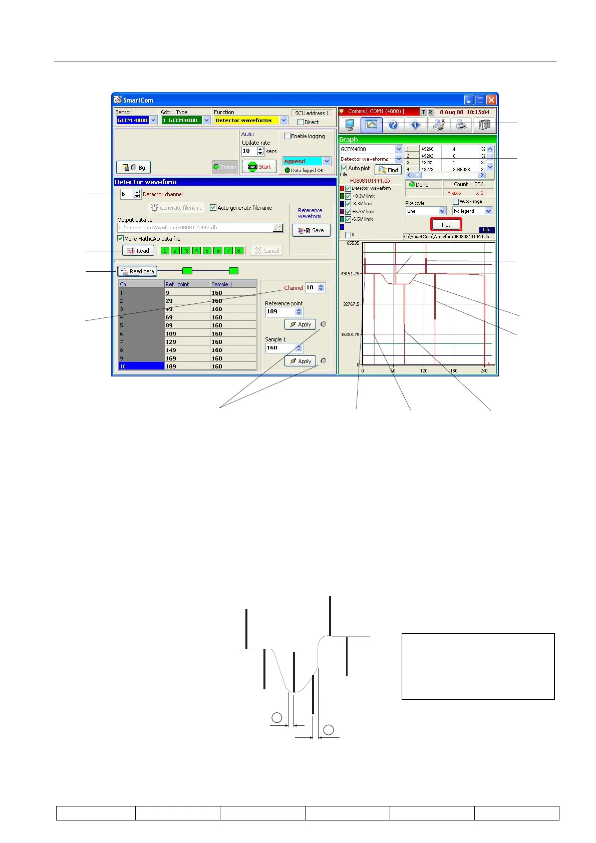
a. Select detector in the detection channel box (1).
b. Select ‘Graph’ (2).
c. Select ‘GCEM4000’ and ‘Detector waveforms’ (3).
d. Read a detector waveform by pressing ‘Read’ (4); wait for the waveform to be displayed
opposite.
e. The displayed signal (5) should look as shown below, with the six lines protruding form it. These
lines denote the three start and three stop points of the sampling. At this point the sampling
positions may need to be adjusted; this can be checked as follows:
1
2
Space 1 should equal space 2.
(1)
(2)
(3)
(5)
Sample 3
start
Sample 3
end
Sample 2 start
Sample 2 end Sample 1 end Sample 1 start Comms. lights
(4)
(6)
(7)
Looking at the sample detector
wave form, it can be seen that
spaces (1) and (2) are equal;
this must also be achieved on
the displayed signal.