Technical Manual Page 46 CODEL
OPS.080 Issue : C Rev. : Date : 16/7/08 Doc. i/d : 0080/6 Ref. : 080040
The data now displayed relates to the complete output set for a particular channel and is configured at the
factory.
At this point you should understand that this section is factory set and should be left alone
under nearly all circumstances.
Current output
Abs. data location : the memory location of the source of the current output data
0 - 4mA : selects the starting value (in mA) for zero output
Data invalid : Zero
Averaging value : the time period over which the output data is averaged in 0 - 256 steps. Each
step is 3 seconds and is input in hexadecimal. Some key values are shown
below.*
Span : the upper point of the output data
Zero : the lower start point of range
Relay output
Abs. data location : the memory location of the source of the alarm output data
Averaging value : the time period over which the output data is averaged as described above
Direction : Normal = NO and Reverse (failsafe) in NC
Alarm level : alarm threshold in decimal
Source : 2 byte
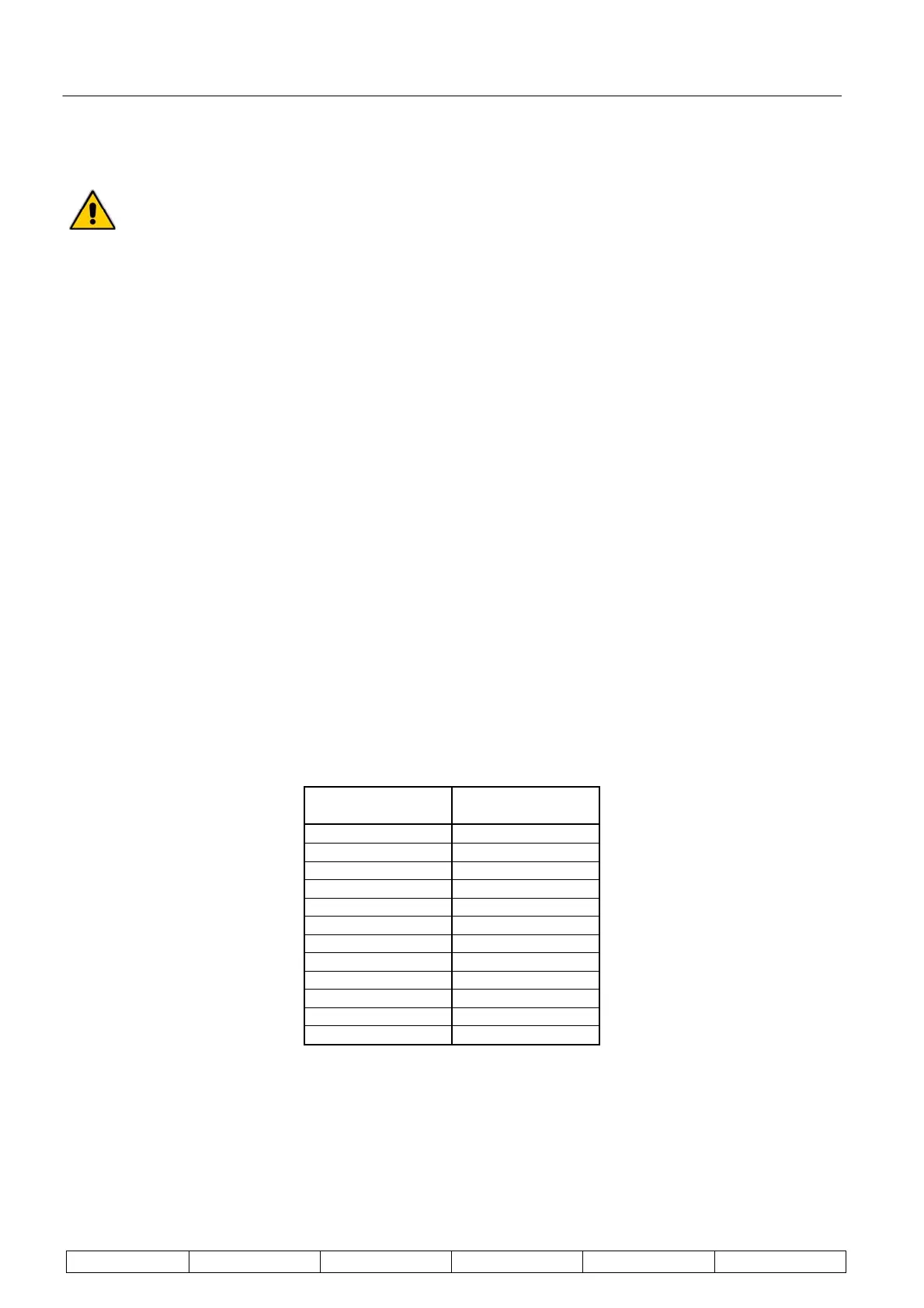
* Averaging time values
Time in minutes Hexadecimal
value
1 0014
2 0028
3 003C
4 0050
5 0064
6 0078
7 008C
8 00A0
9 00B4
10 00C8
11 00DC
12 00FO
To reveal the channel configuration of the GCEM4000 using SmartCEM, select ‘GCEM400’ from the ‘Sensor’ list
and from the ‘Function’ list select ‘Gas Channel Config’ as shown below. Click on the ‘Read’ button to identify
channels 1 to 7.