INSTALLATION & USER'S MANUAL CLITE2 Page 19
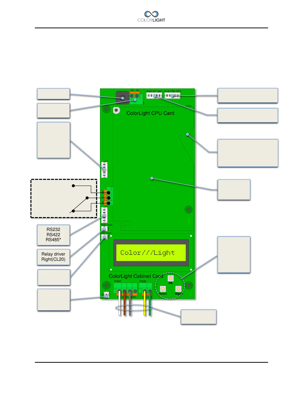
Cabinet card 9.3
Colorlights control system is stable and future-proof and the cabinet card is equipped with a
number of inputs and outputs as to allow the communication with the searchlight but also
communicate with computers, radio receivers, limit switches (via optocoupler) etc.
On the output side, we have relay controlled alarm output (NO, NC) for external alarm handling
and outputs for controlling relays (via optocoupler).
RS422
Opto 1A ->
Opto 1C <-
Opto 2A ->
Opto 2C <-
24Vdc
0V
fan in box
Signalcable
to searchlight
Menu
navigation
See:
Menu
Left LED Controlsignal
0-10V
Right LED Controlsignal
0-10V
CPU Card
CAN H (green)
CANL (yellow)
+24Vdc (brown)
0V (white)
*
1
Standard setting.
*
2
Wire is installed but has no function on CLITE2.
(connects with patchcable
to keystone pass-through