INSTALLATION & USER'S MANUAL CLITE2 Page 23
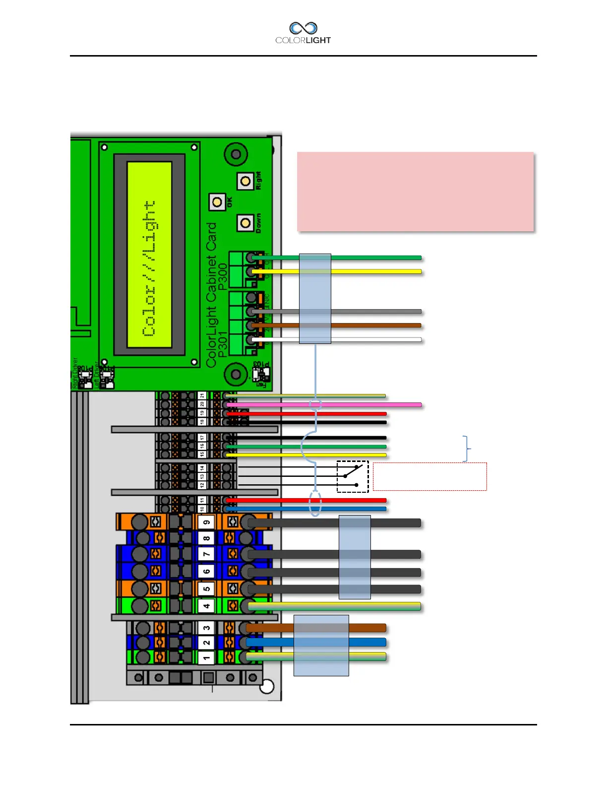
CLITE2 electrical-box connection (100-240VAC) 9.5.1
This connection diagram shows our standard connection for CLITE2 with electrical box supplied
with DC voltage. Deviations may occur for customized solutions.
#3- L
#2- N
#1- Earth (PE)
#9- LD02 + (wire marked “4”)
#7- LD02 – (wire marked “3”)
#6- LD01 – (wire marked “2”)
#5- LD01 + (wire marked “1”)
#4- Earth (PE)
#11 – Control signal for LED (RIGHT)
#10 – Control signal for LED (LEFT)
#14 – Alarm output (NC)
#13 – Alarm output (COM)
#12 – Alarm output (NO)
#17 – GND
#16 – RS232/485*
1
#15 – RS232/485*
1
#19 – 24Vdc for panels, Ethernetswitch
#18 – 0V
#20 – 24Vdc for cam window heater
CAN H to searchlight electronics
CAN L to searchlight electronics
Fan control voltage UV*
2
24Vdc to searchlight electronics
0V to searchlight electronics
CABLE
100-
*
1
Standard setting.
*
2
Wire is installed but has no function on CLITE2.
integrated bridge-
IMPORTANT
The wiring on this page is valid only for
CLITE2 systems delivered from May 2016 with
Searchlight or Ebox serial number from
16003863
-
See the system wiring diagram for more details.