InteliMains
NT
, SW version 3.0
InteliMains-NT-BTB-3.0-Reference Guide.pdf, ©ComAp – June 2013
NOTE:
If +PWR BOUT is used, it increases power consumption of the controller.
3.9.2 IM-NT-BB and IM-NTC-BB
This portion of Instalation instructions is dedicated to the
InteliMains-NT-BaseBox and InteliMains-NTC-BaseBox
controllers without built-in display. If you have version with built-in
display of the controller, please refer to the section 3.8.1.
It is possible to use binary outputs as low side switch or high side switch in BaseBox type of controller.
For correct wiring in both cases please refer to the following diagrams.
Low side switch High side switch
Binary outputs
+ -
BO1
Battery 24V
DC
+ -
From
microprocessor
Internal
Binary outputs
+ -
BO1
Battery 24V
DC
+ -
From
microprocessor
Internal
CAUTION!
Both power supply sockets for binary outputs need to be connected to ensure proper function of binary
outputs.
Never use DC relays without protection diods!
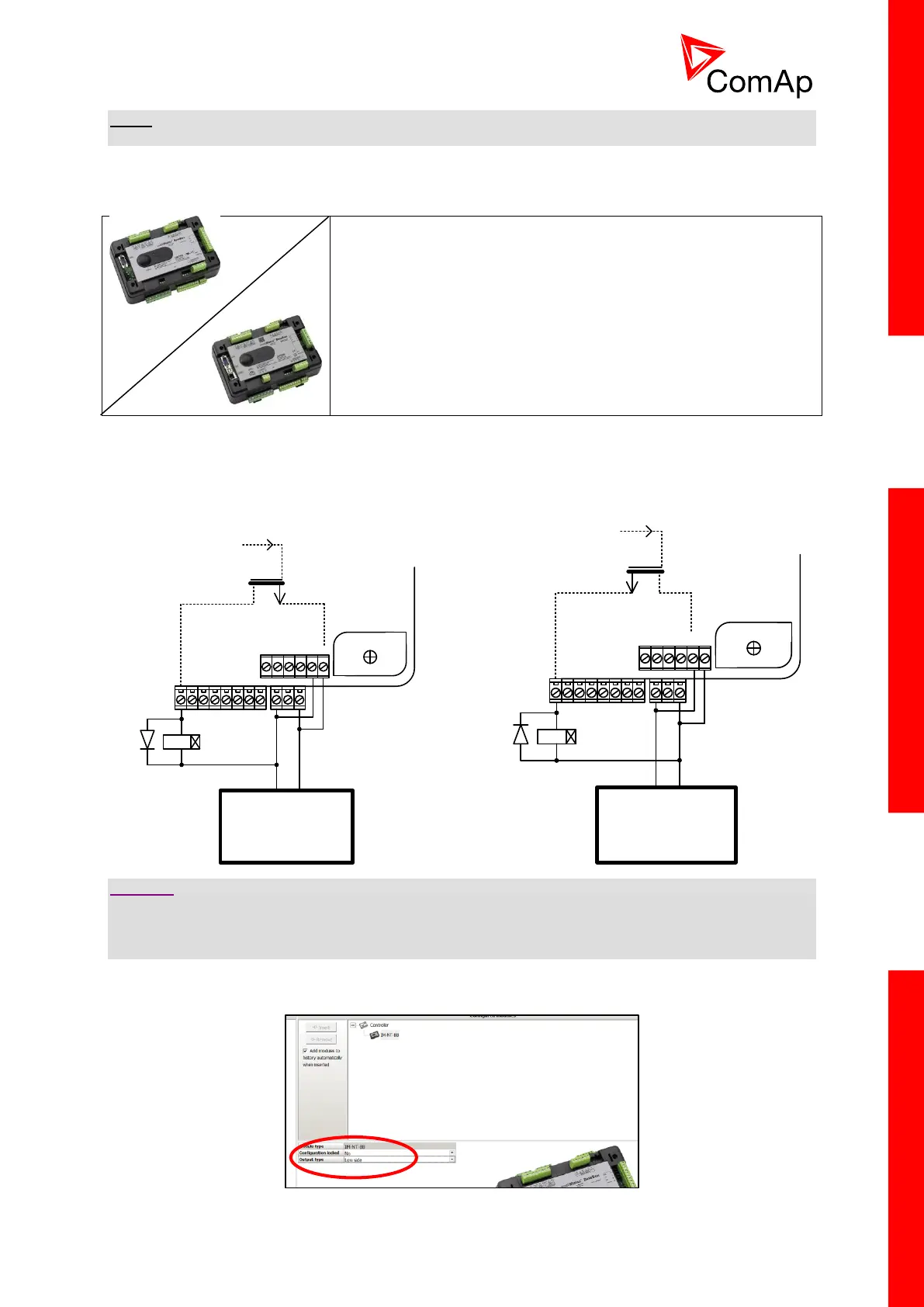
Low side or High side function of binary outputs can be chosen in configuration tool GenConfig in
Modules tab. This configuration is used for all binary inputs available on the controller.