InteliMains
NT
, SW version 3.0
InteliMains-NT-BTB-3.0-Reference Guide.pdf, ©ComAp – June 2013
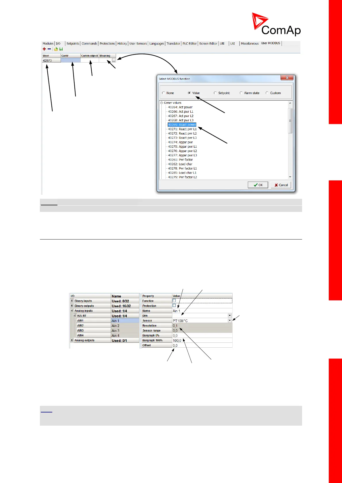
User Modbus register number
Standard Modbus register number
Communication object number
Value, Setpoint, Alarm state
Select type
Select object
NOTE:
User MODBUS function is not available for IM-NT-GC controller.
7.19 Analog Input Sensors and User Sensors
Controller and/or some extension modules allow connection of sensor outputs to Analog Inputs. There
is whole variety of common sensor output characteristics prepared in configuration by default.
Although if there is sensor that is not in the list, it is possible to prepare custom characteristics (up to
16) with up to 31 definition points.
Name of the
Analog Input
Dimension
Connected Sensor
(default and user
sensors)
Resolution and Range of the sensor (in
some cases this is fixed by sensor type
and cannot be changed)
Interpretation of
the received value
in bar graph form
Offset of the
received value
Figure: Sensor adjustment in GenConfig
Default sensors: PT100/°C, PT1000/°C, NI1000/°C, PT100/°F, PT1000/°F, NI1000/°F,
4-20mA active, 0-2400ohm, 0-2.4V, Tristate
HINT
There is “electronic” type of sensor available for Shared Analog Inputs which can be used to interpret
shared data over CAN bus.