ID-FLX Lite & Telecom Global Guide
39
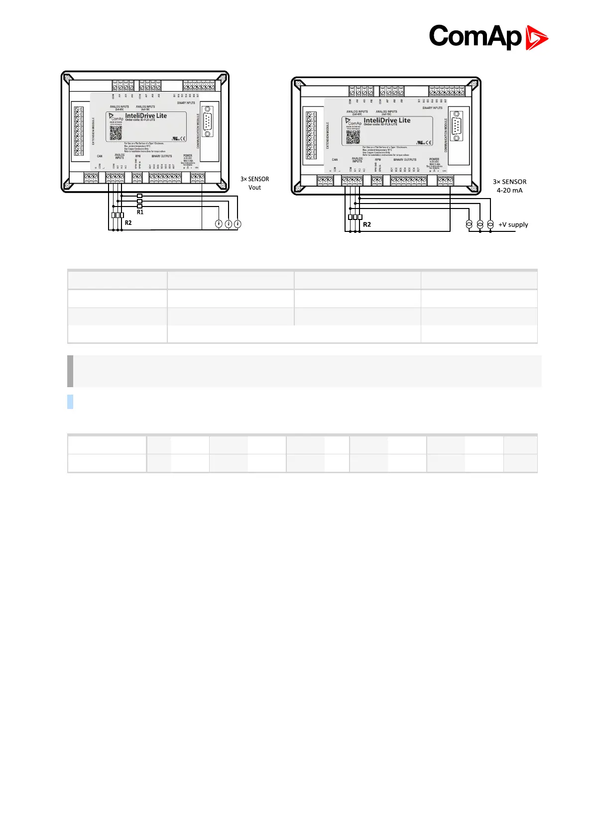
Analog input R1 R2 Curve
0 – 10 V 150 Ω [1 %, 0.5 W] 100 Ω [1 %, 0.5 W] AI 0-10 V.CRV
0 – 30 V 680 Ω [5 %, 2 W] 100 Ω [1 %, 0.5 W] AI 0-30 V.CRV
4 – 20 mA R = 160 Ω [1 %, 0.5 W] AI 4-20 mA.CRV
Recommended values
IMPORTANT: Please note that external resistors disconnection, connection incorrect resistors or
input voltage value during operation may cause an analog input destruction.
Example: VDO pressure sensor 0 – 6 bar with linear voltage output 0 – 10 V
Vout [V] 0 1 2 3 4 5 6 7 8 9 10
P [bar] 0 0.6 1.2 1.8 2.4 3 3.6 4.2 4.8 5.4 6
Conversion table
Modify one of analog input in LiteEdit configuration and load curve AI 0-10V.CRV
Than you can change resolution and measured value name witch is default displayed at V (volts).
For example if you have connected pressure sensor and his output voltage is 5 V for pressure 3 bar you can
change value ‘V’ in column “Dim:” to ‘Bar’ and by sensor specification adjust all corresponding values in this
column. In this case you can change the value at row 6. from 5 to 3.