C4-C5XL MK3 O&S
5-6
C4000MK3-OM-EN-11
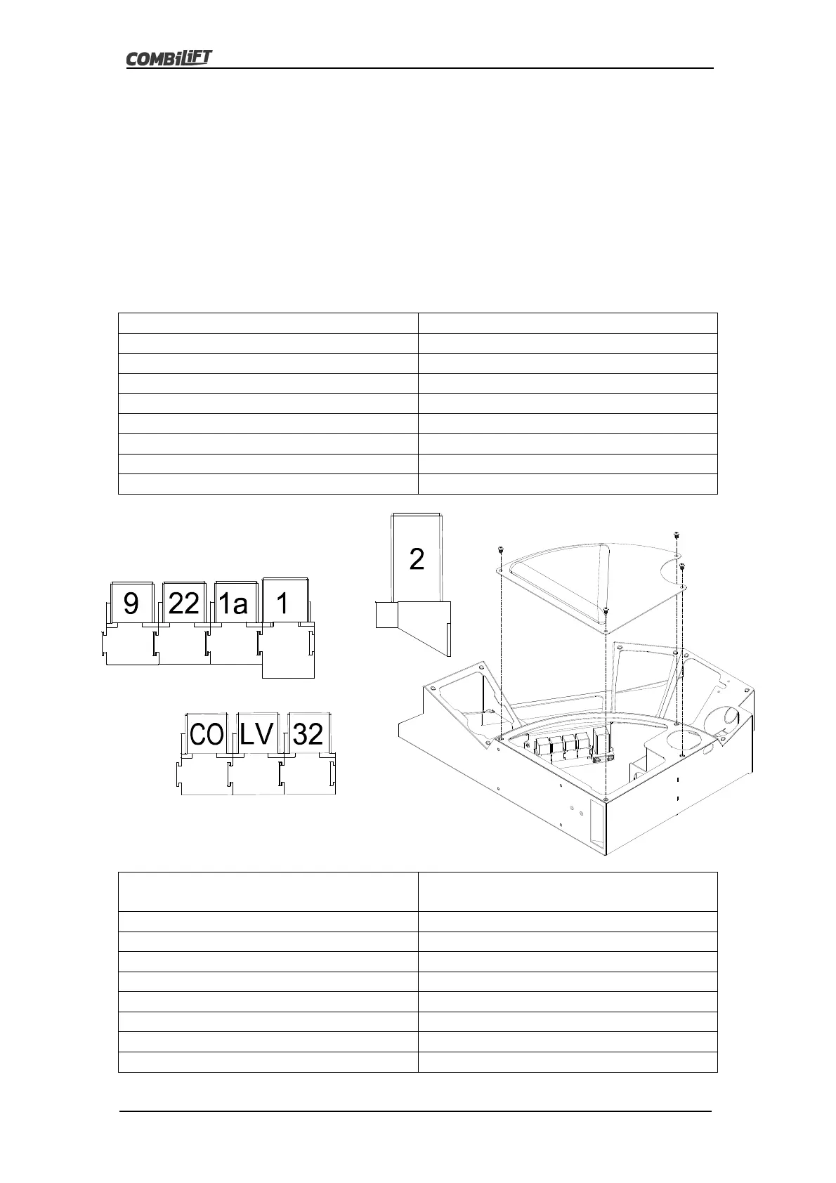
5.6: Relay Layout
There are a number of relays involved in the electrical control system of the
truck. These relays are located inside the dash in the cabin of the Combilift. To
access the relays remove the dash top plate by removing the four M6x10
dome head bolts in the corners of the plate as shown in the diagram below.
The relay layout is also shown in the diagram below. The relays have the
following functions:
Rela
Function
1 Starte
1a Neutral Cut-Off
2 Glow Plu
Timer Rela
Diesel Onl
9 Steerin
Solenoid Suppl
22 Work Li
hts
Spot Li
hts
32
uxiliar
H
draulic Function Solenoid
LV Valve Bank Lock Valve Solenoids
CO En
ine Temperature Cut-out
Relays For Optional Extras
Not Shown Above
Function
23 Indicators - road li
hts
26 Brake - road li
hts
27 Guide Roller Li
ht
31 Inch pedal park brake switch
32a
uxiliar
H
draulic Function Solenoid
33 Extra Spotli
hts
On Mast
34 Extra Oil Coole
45
ir Seat