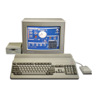
Do you have a question about the Commodore Amiga A2000 and is the answer not in the manual?
| Manufacturer | Commodore |
|---|---|
| Type | Desktop |
| Release Year | 1987 |
| CPU | Motorola 68000 |
| ROM | 256 KB |
| Color Depth | Up to 4096 colors |
| Operating System | AmigaOS |
| Power Supply | 200W |
| Model | A2000 |
| RAM | 1 MB (expandable to 8 MB) |
| Chipset | Original Amiga (OCS) |
| Graphics | OCS |
| Sound | 4 channels, 8-bit resolution |
| Storage | 3.5" floppy drive (880 KB), optional hard drive |
| Ports | Serial, Parallel, Floppy, Video, Audio, Mouse, Keyboard |
| CPU Speed | 7.16 MHz (NTSC) or 7.09 MHz (PAL) |
| Display Resolution | 320x200 to 640x400 (NTSC), 320x256 to 640x512 (PAL) |
Details the key hardware components of the Amiga computer system.
Explains the main processor and the specialized custom chips enhancing system performance.
Provides essential warnings and guidelines for direct hardware programming.
Introduces the Copper's instruction set: WAIT, MOVE, and SKIP for display control.
Describes location registers, jump address strobes, and the control register (COPCON).
Details how to initialize and halt the Copper coprocessor for stable display operations.
Explains Amiga's raster display techniques and pixel-based graphics.
Covers defining playfield characteristics like height, width, color, and resolution.
Explains how bit-planes are used to define pixel colors and the number of colors available.
Describes how to set the on-screen display area by defining window start and stop positions.
Explains techniques for smooth vertical and horizontal playfield movement.
Details how to define sprite characteristics like size, shape, color, and screen position.
Outlines the steps to create a sprite's data structure in memory, including control and color words.
Explains how to display sprites using automatic DMA mode and the necessary steps involved.
Describes how to reuse sprite DMA channels for more objects or complex images within a single display field.
Explains the basic principles of sound waves, frequency, amplitude, and timbre.
Covers the essential steps for creating steady tones, including waveform definition and DMA setup.
Details how to specify the sampling period to control the frequency and pitch of sounds.
Discusses factors like waveform transitions, sampling rate, and noise reduction for better audio quality.
Explains how the blitter combines data from three sources using logic operations for graphics.
Describes the blitter's ability to shift images and use masks for precise pixel manipulation.
Explains how to move arbitrary rectangles of data between bitplanes or positions.
Explains the flag used to check if the blitter has finished its operation before accessing results.
Details how to control the display order of objects like playfields and sprites for visual layering.
Explains how hardware detects overlaps between objects to trigger events.
Covers the system's interrupt handling, including types and control registers.
Explains how Direct Memory Access (DMA) functions are controlled and enabled across various channels.
Describes the nine-pin connectors for various controllers like mice, joysticks, and light pens.
Explains how mouse and trackball inputs are processed using quadrature techniques.
Details the Amiga's disk controller capabilities for MFM and GCR encoded disks.
Covers the keyboard interface, data reception, and keycode assignments.
Blitter control register 0, managing modes like area, line, and shifts.
Bit plane control register for display modes like resolution, interlacing, and color.
Collision control register defining which bit-planes and sprites are included in detection.
Disk DMA data buffer for reading or writing data to the disk.
Sprite 0 position register, controlling the starting screen coordinates.
Sprite 0 control register, defining stop position and attachment options.
Details the pin designations and functions for the Agnus custom chip.
Lists the pin assignments and functions for the Denise custom chip.
Provides pinout details and functions for the Paula custom chip.
Describes the Amiga's memory layout, including chip RAM, expansion memory, and ROM addresses.
Details the 25-pin connector for parallel devices like printers, including pin assignments.
Covers the 25-pin D-type connector for RS-232-C serial communication.
Explains how digital joystick inputs are encoded and read via the JOYxDAT registers.
Introduces the 8520 CIA chips and their general purpose I/O capabilities.
Provides the register map and addresses for the CIAA chip.
Details the register map and addresses for the CIAB chip.
Explains the protocol for dynamic assignment of address slots to expansion boards.
Describes board identification information and AUTOCONFIG registers at configuration time.
Details the serial data transmission protocol between the keyboard and the computer.
Explains the hexadecimal keycodes representing key presses and releases.
Describes the steps involved in initializing the keyboard and computer connection.
Introduces the 23-pin connector for MFM data devices and driver control.
Explains the signals used for controlling disk drives like motor, head movement, and selection.
Describes the method for identifying attached disk drive types via an ID sequence.
An include file defining register names for hardware examples, referencing custom.i.