Section 10–Device Configuration-Antennas Multiple Integrated Actuators ATC200-LITE-USB Teletilt
®
RET System
10-2 October 2014 Bulletin 639536 • Revision L
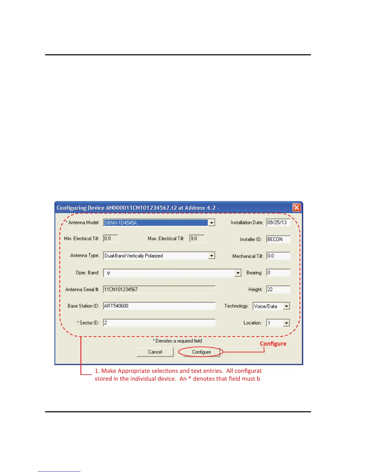
Note the following in Figure 10-2:
• The ID of the device to be configured is displayed in the title bar of the dialog box.
• Devices that have never been configured before will display blank fields for most param-
eters.
• Actuators that have been factory installed on an antenna are pre-configured to include the
antenna model number, antenna type, and antenna serial number. The remaining fields
such as Installation Date, Mechanical Tilt, Bearing, Height, Sector, Location, Oper. Band
(for AISG 2.0 actuators) or Freq. Band (for AISG 1.1 actuators), Technology, Station ID, and
Installer ID will need to be configured.
• Configuration items marked with an asterisk are required; saving a new configuration will be
disabled if any of these fields are blank.
• The Installation Date field is handled differently from all other configuration items. Although
this field is not required, if no installation date has been saved on the actuator, the program
will suggest the current date as the default.
• AISG 2.0 Protocol Mode allows a 32 character Station ID.
Figure 10-2. Device Configuration Screen.
ion data is
e completed.
2. Click .