Section 2–Controller Setup ATC200-LITE-USB Teletilt
®
RET System
2-7 October 2014 Bulletin 639536 • Revision L
Figure 2-8. ATC Lite Program Icon.
Figure 2-9. ATC Lite Program Main Screen.
2.4 Program Startup
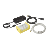
Connect the desired length RET control cable be-1.
tween the controller’s AISG connector and the first
device in the RET system (or actuator that is to be
tested before the antenna is mounted on the tower).
Double-click on the ATC Lite icon that was placed on 2.
the computer’s desktop during program installation
(Figure 2-8).
The controller program will open to its main screen (Figure 2-9).3.
Select 4. Communication from the main menu to view the communication port used for the con-
nection. See Figures 2-10 and 2-11 for examples.
If you desire to exit the program at this time, select 5. File
→Exit from the main menu or click on the
X in the far top right.