Era
™
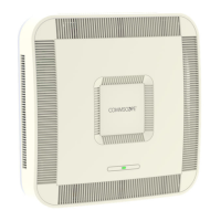
Medium Power Carrier Access Point Installation Guide M0201AJB
Page 4 © October 2018 CommScope, Inc.
Era System Overview
ERA SYSTEM OVERVIEW
Era™coordinateswirelesscapacitythroughouttheentirecoverageareaviaasinglecentralizedhead-end
locationorfromanoperator’sexistingC-RANhub.BasedonION
®
-E,Eraoperatesonthesamecost-efficient
standardITcablingasION-EandiscompatiblewithION-Edeployments.Erasystemsbringtogetherlicensed
wirelessandpower,plusGigabitEthernetforWiFiintoonewirelesssystemthatcanscaletobuildingsizeand
istechnologyandspectrumagnosticandadaptive.AnErasystemcomprisesthecomponentslistedbelow.
• CentralAreaNode(CAN)—providesserver-levelcontrolandprimarysignaldistribution.Itcombines
thesignalsfrommultipleoperatorsanddistributesthosesignalswithinavenueormultiplevenues.
TherearetwoconfigurationmodesavailablefortheCAN:ClassicandSwitching.
– TheClassicCANconfigurationisappropriateforwhenalltheBTSandBasebandsourcesarelocated
inacentralizedspaceinthesamevenueastheClassicCAN.YouinstallRFDonor(RFD)Cardsand
CPRIDigitalDonor(CDD)CardsinaClassicCAN,whichdigitizestheanalogBTSsignalsfromtheRFD
CardsandcombinesthosewiththeBBUCPRIdigitalsignalsfromtheCDDCards,andthendistributes
theRFsignalstotheTENs.TheTENsthenprovidetheRFsignalstotheAccessPoints(APs).The
ClassicCANalsosupportsAPsthataredirectlyconnectedtoCATorOPTCardsinstalledintheClassic
CANchassis.Wide-areaIntegrationNodes(WINs)arenotsupportedbyaClassicCAN.Usershavefull
andflexiblecontrolofallsignalroutingviatheEraGUI.
– TheSwitchingCANconfigurationisappropriateforwhenWINsarerequiredtoallowoperatorsto
bringinbasebandsignalsfrommultipleremotelocationstofullyleveragetheC-RANarchitecturein
theirhubs.AlloperatorBasebandsignals(analogBTSandBBUCPRI)aresuppliedtotheSwitching
CANbytheWINs,sonoRFDorCDDCardscanbeinstalledintheSwitchingCAN.TheSwitchingCAN
thencombinesthesignalsfromallWINsanddistributesthosesignalstotheTENs,andtheTENs
providethesignalstotheAPs.APsarenotdirectlyconnectedtoaSwitchingCAN.Usershavefulland
flexiblecontrolofallsignalroutingviatheEraGUI.
• Wide-AreaIntegrationNode(WIN)—interfacesbetweenaSwitchingCANandRFsources,which
makesC-RANpossibleinErabyallowingoperatorstobringinsignalsfrommultipleremotelocations
kilometersaway.YouinstallRFDandCDDCardsintheWIN,whichtakestheanalogBTSsignalsfromthe
RFDCardsandcombinesthosewiththeBBUCPRIdigitalsignalsfromtheCDDCards,anddistributesthe
RFsourcestoaSwitchingCAN.
• TransportExpansionNode(TEN)—isanexpansionnodeconnectedtotheCANviafiberandcanbe
locatedthroughoutthevenuecoveragearea.AsingleTENcansupport,dependentontheAPtypeand
poweringmethod,12to32AccessPoints(APs),whichgreatlyreducesthenumberoffiberrunsbetween
thehead-endandeachAP.
• AccessPoint(AP)—connectsaClassicCANorTENtoantennasorotherwirelessdevices.Onthe
downlink,anAPconvertsdataarrivingattheAPtoanalogsignalsandsendsthemtoanantenna.Onthe
uplink,receivedsignalsaredigitizedandserializedintodatastreamswhicharesentbacktotheClassic
CANorTEN.APssupportGigabitEthernetpass-throughforWiFi,IPcameras,orotherdevicesinaddition
towirelessoveracommoncable.AnAPcanbeanyoftheUniversalAccessPointsorCarrierAccessPoints.
This guide uses “CAN” to collectively refer to Central Area Nodes. When information pertains to a specific
CAN mode, “Classic CAN” and “Switching CAN” will be used.
This guide uses “Access Point (AP)” to collectively refer to the Universal Access Points (UAPs) and the
Carrier Access Point (CAPs), and “Fiber APs” to collectively refer to Fiber CAP Ls and CAP Ms. When
information pertains to a specific AP type, that AP will be identified.