Ruckus ICX 7450 Switch Hardware Installation Guide 59
Part Number: 53-1003899-09
The Ruckus ICX 7450-48F has the following LEDs on the front panel:
• Two management port monocolor status LEDs (green) for speed and link/activity
• Two power supply unit (PSU) bicolor status LEDs (green and amber) labeled PSU1 and PSU2
• One DIAG bicolor status LED (green and amber)
• One MS bicolor status LED (green and amber)
• Three MOD monocolor status LEDs (green)
• Ten stack ID (stack ID) monocolor status LEDs (green)
• 48 1 GbE SFP port bicolor status LEDs (green for 1 GbE and amber for 10/100 Mbps Ethernet) that indicate 1 GbE or 100
Mbps mode of operation
1G SFP module LEDs:
• Four 1 GbE SFP port bicolor status LEDs (green for 1 GbE and amber for 10/100 Mbps Ethernet) which indicate 1 GbE or
10/100 Mbps Ethernet mode of operation
10G SFP+ module LEDs:
• Four 1/10 SFP+ GbE port bicolor status LEDs (green for 10 GbE and amber for 1 GbE) which indicate 1 GbE or 10 GbE mode
of operation
40G QSFP+ module LEDs:
• One 40 GbE QSFP+ port bicolor status LED (green for 1x40 GbE and amber for 4x10 GbE) which indicates 1x40 GbE mode
of operation
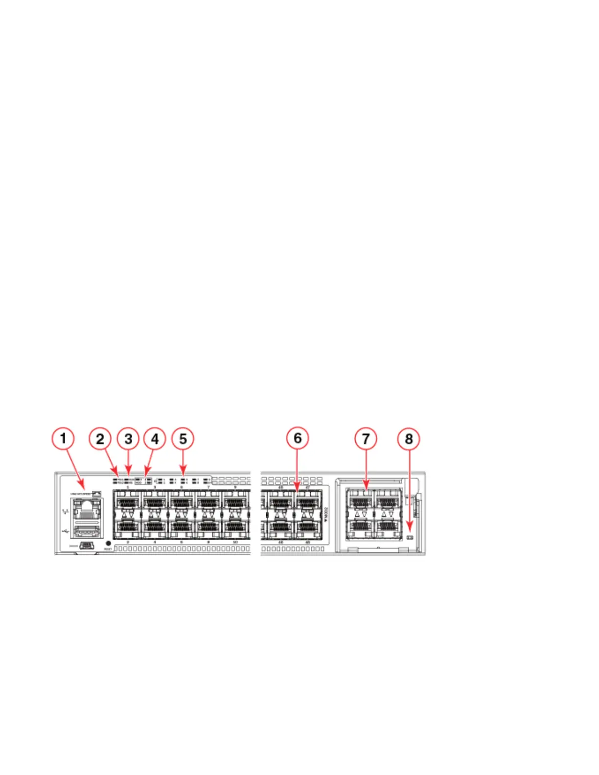
Figure 47 shows the LEDs on the Ruckus ICX 7450-48F front panel. The up-arrow port status LEDs for the 10 GbE ports correspond
to the upper, odd-numbered ports; the down-arrow port status LEDs correspond to the lower, even-numbered ports.
FIGURE 47 Ruckus ICX 7450-48F front-panel LEDs
1 Management port speed and link/activity LEDs 5 Stack ID LEDs
Indicates stack unit identifier (1-12).
2 PSU1 and PSU2 status LEDs
PSU1 corresponds to the right power supply slot
on the rear panel and PSU2 to the left power
supply slot, as viewed from the rear.
6 Ports 1-48 speed and link/activity LED
3 DIAG (diagnostic) status LED and MS (stacking
configuration) status LED
7 MOD2 1/10 GbE module speed andl ink/activity
LEDs
4 MOD (media expansion module) LEDs. Module 2
is located on the right side of the front panel.
Module 3 and 4 are the right and left stacking
modules on the rear panel, as viewed from the rear.
8 MOD2 1/10 GbE power LED
 Loading...