A1000 INSTALLATION, OPERATION, & MAINTENANCE MANUAL
February 2016 | 256574-ENG
R01 4-1
4 CHAMBER INSTALLATION
Once a suitable location is chosen and prepared, the required utilities connections can be made.
4.1 Connecting the Chamber
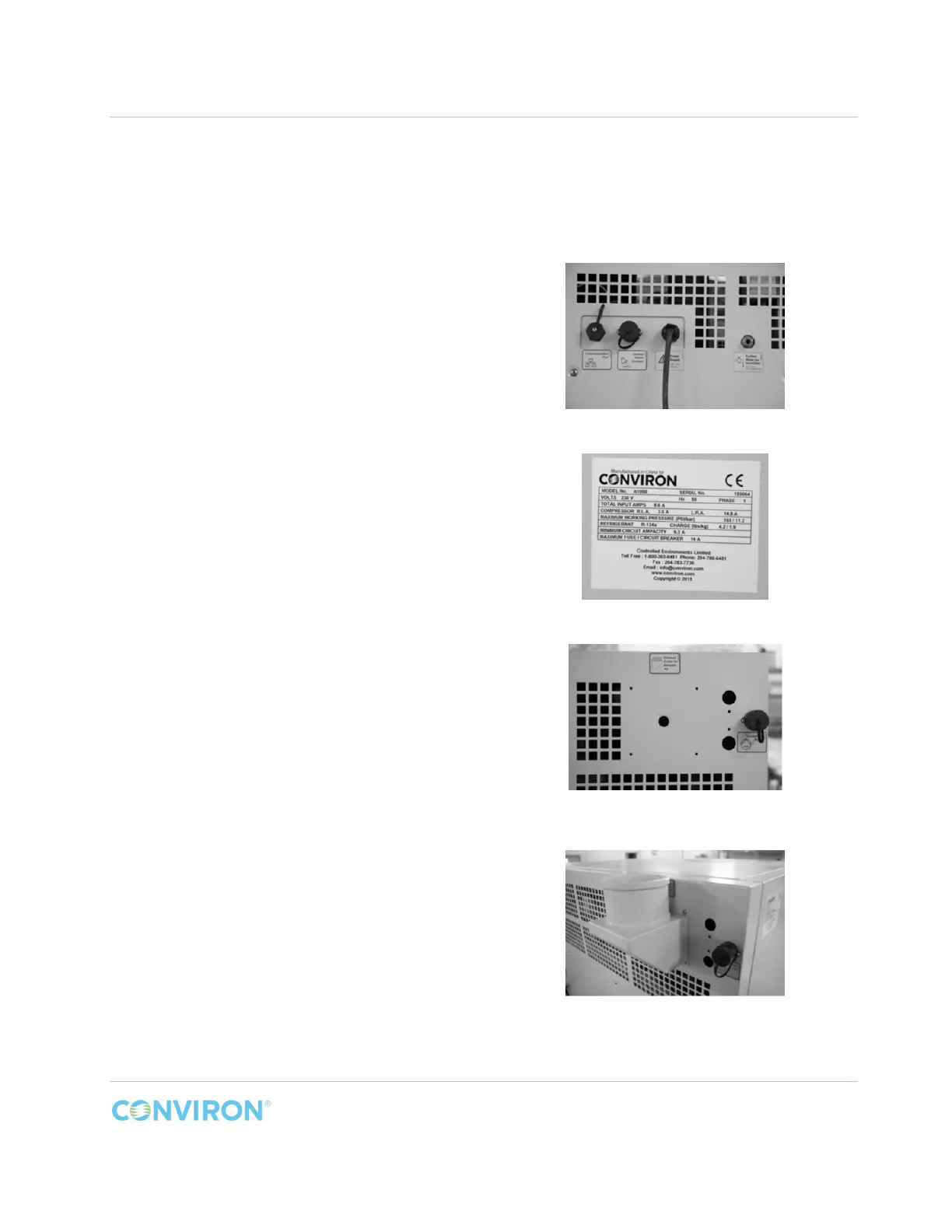
The A1000 is provided with the following
connections on the top right rear corner of the
chamber (Figure 4-1);
1. a Communication Port
2. a Central Alarm Contact connection to
monitor the chamber through the building
LAN
3. a 10ft. (3M) power cord, with wall plug
4. a female M6 (or 1/4 inch for the North
American market) compression fitting for a
purified water supply line connection to the
humidifier
Before connecting the chamber to building
electrical service, verify that the service
matches the specified rating on the chamber
serial plate (Figure 4-2), located on the left
hand side of the chamber.
The connections for the optional exhaust collar
and the condensate pump are located in the top
left corner rear corner of the chamber (Figure
4-3).
Figure 4-4 shows the optional exhaust collar
installed onto the rear of the chamber.
Figure 4-1 Chamber Connections
Figure 4-2 Chamber Serial Plate Example
Figure 4-3 Exhaust Collar and Condensate
Pump Connections - Optional
Figure 4-4 Optional Exhaust Collar Installed