February 2016 | 256574-ENG R01 vii
LIST OF FIGURES
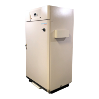
Figure 2-1 Empty A1000 Chamber .................................................................................................... 2-1
Figure 2-2 TC Back Wall Plenum Bottom Support Installed ............................................................. 2-4
Figure 2-3 TC Back Wall Plenum Installed ........................................................................................ 2-5
Figure 2-4 TC Air Shelf Support Clip Installed .................................................................................. 2-6
Figure 2-5 TC Bottom Air Shelf Installed ........................................................................................... 2-6
Figure 2-6 TC Lamp Canopy Supports Detail ................................................................................... 2-7
Figure 2-7 TC Wire Shelf Supports Detail ......................................................................................... 2-8
Figure 2-8 TC Kit Installed ................................................................................................................. 2-8
Figure 2-9 PG Fan and Air Inlet Cavities ......................................................................................... 2-11
Figure 2-10 PC Canopy Air Inlet Filter Installed ................................................................................ 2-11
Figure 2-11 PG Canopy Fan Pre-installation .................................................................................... 2-12
Figure 2-12 PG Canopy Fans Installed ............................................................................................. 2-12
Figure 2-13 PG AC/DC Converter Electrical Connections ................................................................ 2-13
Figure 2-14 PG AC/DC Converter Installed ...................................................................................... 2-13
Figure 2-15 PG Back Wall Plenum Bottom Support Installed ........................................................... 2-14
Figure 2-16 PG Back Wall Plenum Installed ..................................................................................... 2-15
Figure 2-17 PG Lamp Canopy Supports ........................................................................................... 2-16
Figure 2-18 PG Lamp Canopy Installed ............................................................................................ 2-16
Figure 2-19 PG Lamp Canopy Plug Connection ............................................................................... 2-17
Figure 2-20 PG Unifloor Screw Installation ....................................................................................... 2-18
Figure 2-21 PG Unifloor Installation .................................................................................................. 2-18
Figure 2-22 PG Wire Shelf Supports Detail ....................................................................................... 2-19
Figure 2-23 PG Kit Installed .............................................................................................................. 2-19
Figure 2-24 IN Back Wall Plenum Bottom Support Installed ............................................................. 2-21
Figure 2-25 IN Back Wall Plenum Installed ....................................................................................... 2-22
Figure 2-26 IN Bottom Shelf Installed ............................................................................................... 2-23
Figure 2-27 IN Wire Shelf Supports Detail ........................................................................................ 2-23
Figure 2-28 IN Lamp Supports Installed onto the Fixture ................................................................. 2-24
Figure 2-29 IN Single Lamp Fixture per Shelf Installed .................................................................... 2-24
Figure 2-30 IN Multiple Lamp Fixture Installation Detail ................................................................... 2-25
Figure 2-31 IN Kit Installed ................................................................................................................ 2-25
Figure 2-32 AR Back Wall Plenum Bottom Support Installed ........................................................... 2-27
Figure 2-33 AR Back Wall Plenum Installed ..................................................................................... 2-28
Figure 2-34 AR Shelf Supports Installed for Maximum Growth Height ............................................. 2-29
Figure 2-35 AR Lamp Canopy Installed ............................................................................................ 2-30
Figure 2-36 AR Bottom Shelf Location and Supports Detail ............................................................. 2-31
Figure 2-37 AR Kit Installed ............................................................................................................... 2-31
Figure 4-1 Chamber Connections ..................................................................................................... 4-1
Figure 4-2 Chamber Serial Plate Example ........................................................................................ 4-1
Figure 4-3 Exhaust Collar and Condensate Pump Connections - Optional ...................................... 4-1