Security House,
Vantage Point Business Village,
Mitcheldean,
Glos. GL17 0SZ
Tel: 01594 541900
www.cooperfire.co.uk
Installation Guide for
3 Channel Input/Output Unit
CIO351
CIO351 - Specification:
Installation:
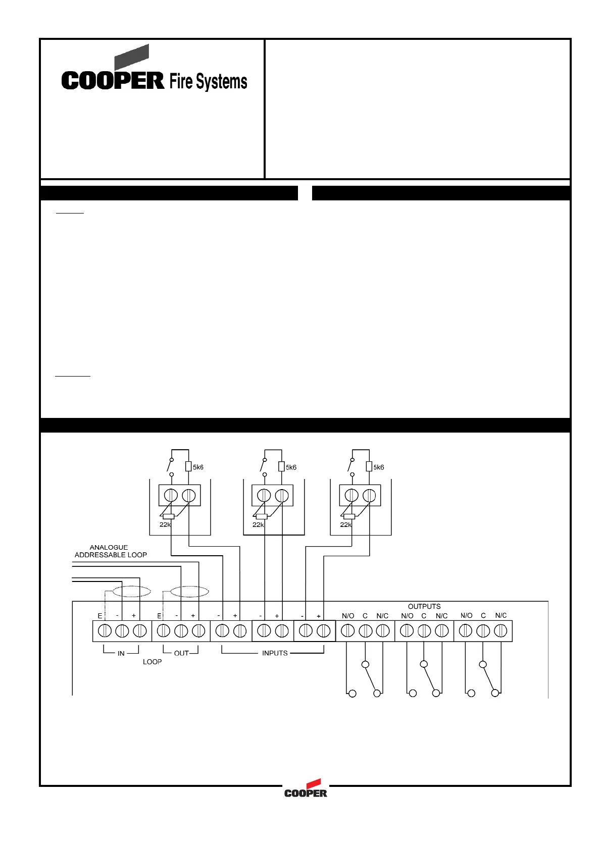
Wiring Schematic:
DOC. REF.: PINSTCIO351
Notes:
1. Cable earth screen must be connected to its adjacent earth terminal.
2. The end of line resistor must always be fitted, even if inputs are not used.
3. Input circuits are monitored for wiring open and short circuit.
4. Output relays are volt free-changeover contacts and are not monitored.
Wiring
Each unit terminal connector is suitable for clamping a
single cable conductor up to a maximum of 2.5mm².
General
Addressing of the unit is not required (see control panel
operation for details)
18 to 30Vdc310
310ìA
Auto addressed
1A @ 30V resistive
0.5A inductive
50Vac or 30Vdc
-10 to +60C
0 to 95% non condensing
IP65
BS5839:Pt 1 (installation)
CE Marked
PC\ABS
180(w)x129(h)x60(d) mm
0.5 to 2.5mm²
Draka - FIRETUF
Pirelli - FP200
MICC
18 to 30Vdc310
310
Auto addressed
1A @ 30V resistive
0.5A inductive
50Vac or 30Vdc
-10 to +60C
0 to 95% non condensing
IP65
BS5839:Pt 1 (installation)
CE Marked
PC\ABS
180(w)x129(h)x60(d) mm
0.5 to 2.5mm²
Draka - FIRETUF
Pirelli - FP200
MICC
ìA
Operating voltage:
Quiescent Current:
Addressing mode:
Output relay contact rating
Maximum switch voltage
Operating Temperature:
Humidity:
IP Rating:
Standards:
EMC:
Materials:
Dimensions:
Cable Size (Min-Max:)
Recommended Cable Types:
Operating voltage:
Quiescent Current:
Addressing mode:
Output relay contact rating
Maximum switch voltage
Operating Temperature:
Humidity:
IP Rating:
Standards:
EMC:
Materials:
Dimensions:
Cable Size (Min-Max:)
Recommended Cable Types:
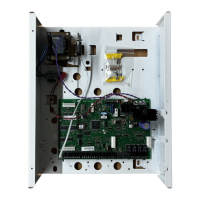
1 Remove the front cover of the unit
2 Remove the internal PCB
3 Drill out the required holes for cable entries
4 Mount the back box in the required position
5 Refit the internal PCB
6 Install wiring through the pre-drilled holes ensuring
care is taken not to damage the circuit board
7 Connect the unit as per diagram below
8 Fit front cover
105