CAS381 Wall Sounder Specification
Order Codes
CAS381
CAS381/WP
Addressable Wall Sounder
Addressable Wall Sounder IP66
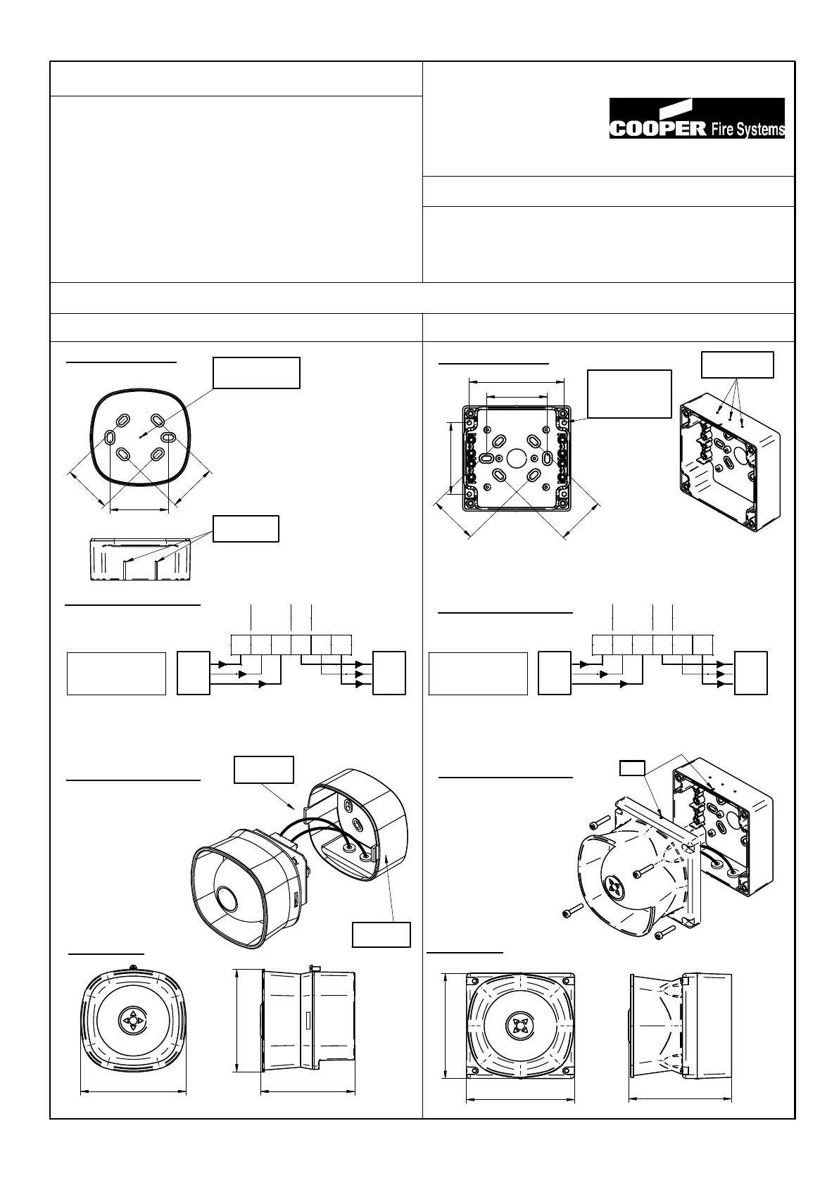
Installation Details
1. Mounting bas e
(ii) Drill out the required
(i) Drill required holes for
fixing holes
cable gland fixing
3. S ounder as s embly
(i) Clip sounder onto base
2. Connection details
Dimens ions
25-5655 B
60
5
0
50
Drill position
for glands
Drill position for
rear cable entry
(iii) Fix to mounting suface
using two suitable screws
SQUEEZE
to remove
SQUEEZE
to remove
108
96
(ii) Ensure cables do
not put stress on
the PCB
105
75
50
5
0
62
1
97
. Mounting bas e
(ii) Fix to mounting surface using four suitable screws
(i) Drill required holes for cable gland fixing (top or bottom)
and ensure cables are correctly sealed for IP66 integrity.
Drill positions
for glands
Use these four
holes to ensure
IP66 integrity
3. S ounder as s embly
(iii) Bolt sounder onto
base
(ii) Ensure cables do
not put stress on
the PCB
Dimens ions
Wall Sounder IP22C
Wall Sounder IP66
RIB
(i) Location ribs must align
on base and sounder
2. Connection details
WARNING: Do NOT use high voltage testers when beacons
or control panel are connected to the system.
Earth screen of cable to be continuous between sounders.
Cooper Fire Systems
Analogue Addressable
Panel
108
110
110
- +
E
LOOP
IN
LOOP
OUT
Earth
IN
- +
E
Earth
OUT
- +
E
LOOP
IN
LOOP
OUT
Earth
IN
- +
E
Earth
OUT
Cooper Fire Systems
Analogue Addressable
Panel
Supply Voltage
Cable Size / type
Standby current
Operating temperature
Material
: 20 ~ 28 Vdc
: 0.5 ~ 2.5mm/ FIRETUF, FP200 or MICC
: < 320 uA
: -10 to +55 degrees C (95%RH)
: ABS/FR Plastic (Wall Sounder)
: ABS/PC FR (Wall Sounder IP66)
Tones
(set by panel)
Sound output @ +/-3dB
(set by panel)
: Low volume : 87dB @ <2mA
: Medium volume : 93dB @ <3mA
: High volume : 100dB @ <6mA
: Continuous 984Hz
: Pulsed 984 / 0Hz pulse 1Hz
: Two Tone 644 / 984Hz @ 1Hz cycle
: Slow whoop 500-1200Hz in 3.5 seconds / 0.5secs gap
WARNING: Do NOT use high voltage testers if ANY
equipment is connected to the system.
Earth screen must be continuous along entire length of loop.
Security House
Vantage Point Business Village
Mitcheldean
Glos.
GL17 0SZ
Tel: + 44 (0) 1594 541900
Note: Polar dispersion information available in the Technical manual.
(Ref: )
111