CASBB384 Sounder/Beacon Base Specification
Supply Voltage
Cable Size / type
Standby current
Operating temperature
Material
Environment Category
Sound output @ +/- 3dB
(Set by panel)
Compliance
Order Codes
CASBB384 Loop Mounted Sounder/Beacon
Base
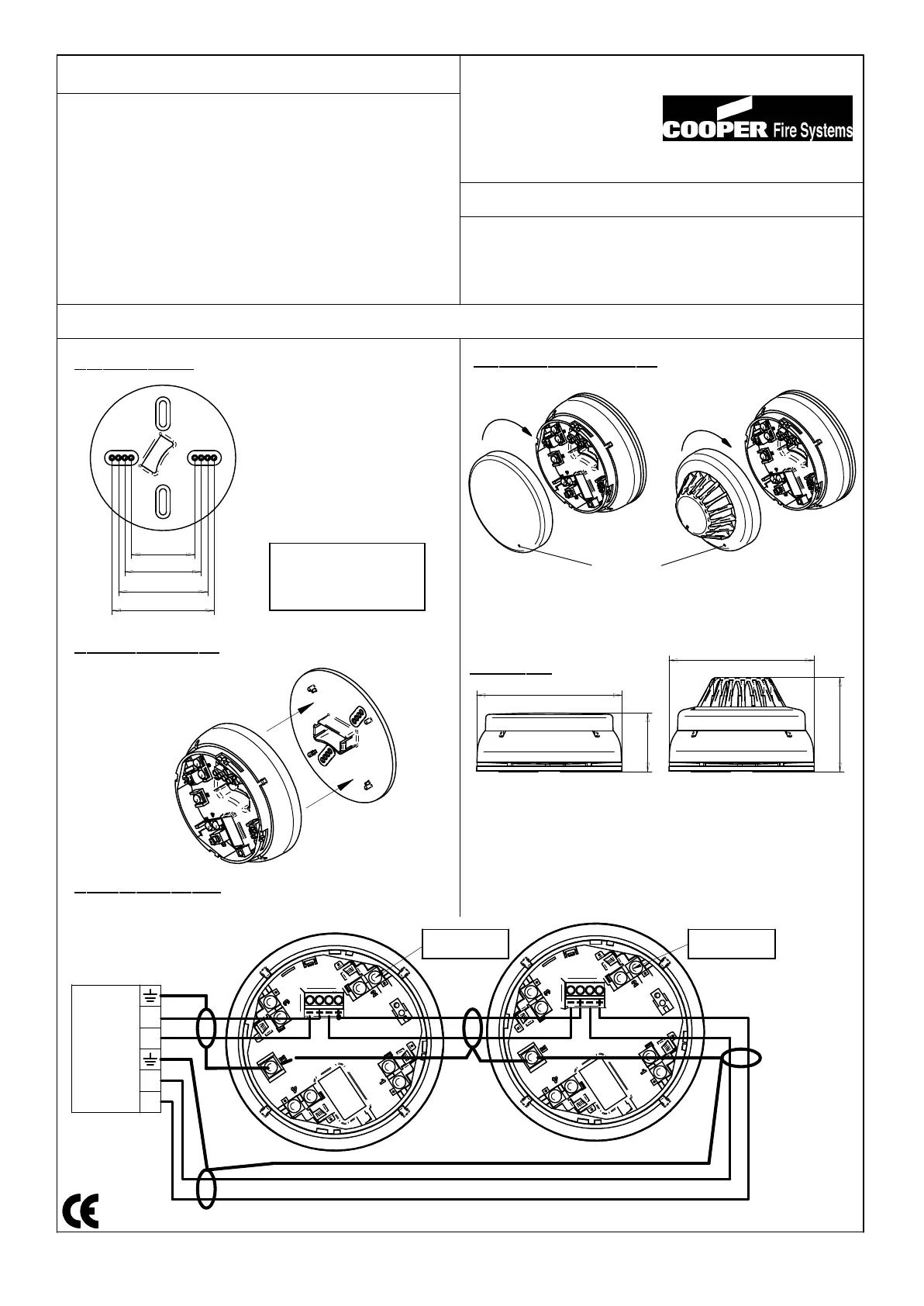
Installation Details
1. Mounting base
(i) Knock-out the required
fixing holes
(ii) Fix to mounting surface
using two suitable screws
If the base deforms on an
un
even surface, loosen
the screws or move to a
more flat position.
2. Sounder assembly
(i) Clip sounder onto base
If sounder needs to be
removed, use a small
screwdriver to unclip.
3. Connection details
Sounder and Cover Sounder and Detector
Dimensions
25-#### Iss A
Remove by inserting a suitable tool
(eg thin screwdriver) into the hole in
the detector or cover, then rotate
de
tector or cover anti-clockwise.
5. Fitting detector or cover
: 18 ~ 32 Vdc
: 0.5 ~ 2.5mm/ FIRETUF, FP200 or MICC
: < 450 uA
: -10 to +55 degrees C (95%RH)
: ABS/PC FR Plastic
: Type A / IP21C
: Low volume : 77dB @ <6.4mA
: Medium volume : 89dB @ <8.0mA
: High volume : 90dB @ <8.5mA
: EN54-3 Fire Alarm Device - Sounder
Loop Start
Loop Finish
Cooper Fire Systems
Analogue Addressable
Panel
S+
S-
F-
F+
Locking tab
release hole
WARNING: Do NOT use high voltage testers if ANY
equipment is connected to the system.
Earth screen must be continuous
along entire length of loop.
Tones
(set by panel)
Flash
: Continuous 910Hz
: Pulsed 910Hz / 0Hz pulse 1Hz
: Two tone 610 / 910Hz @ 1Hz cycle
: Slow whoop 500-1200Hz in 3.5 seconds / 0.5secs gap
:1 Hz
Do not use this
connection
Do not use this
connection
Security House
Vantage Point Business Village
Mitcheldean
Glos.
GL17 0SZ
Tel: + 44 (0) 1594 541900
Note: Polar dispersion information available in the Technical manual. (Ref:M05-024)
####-CPD-####
CE marking under the CPD was affixed on : (See batch code on product)
50
60
70
80
114
46
114
74
114