Configuring and adjusting
Cornelius Deutschland GmbH
Document no. TD2005100
Version 15/03/2019, Index 0
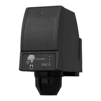
Installation and service manual Dispensing valve
SFV1
24
7.1.4 Restoring the factory settings
Restoring the factory settings resets the fill times of the dispensing valve to the standard fill times, see table Tab. 7-1Fill times fac-
tory setting.
4. Release the “Start & Stop” button (Fig. 41/3) and the button (Fig. 41/1) for the beverage size.
5. Press the “Start & Stop” button (Fig. 41/3).
6. Repeat the process for all beverage sizes.
7. Exit configuration mode by pressing the program button (Fig. 41/2) or the “Start & Stop” button (Fig. 41/3) for 5 seconds.
The “PGM” indicator (Fig. 41/4) goes out.
The fill times for the beverage sizes are reset to the factory settings.
7.1.5 Procedure for non-reactive modules
If the module no longer reacts, please proceed as follows:
1. Check that there is no dirt on the module surface.
If necessary, clean the module surface, see the document “Dispensing valve operator manual”, document no.: TD2005000.
2. Disconnect the base unit from the power supply, see the base unit documentation.
7.2 Adjusting the valves
1. Call up “Standard” configuration mode by pressing the program button (Fig. 41/2) for 5 sec-
onds.
The “PGM“” indicator (Fig. 41/4) lights up.
2. Press the “Start & Stop“ button (Fig. 41/3) and the required button (Fig. 41/1) for the beverage
size simultaneously.
Make sure that you press the “Start & Stop” button (Fig. 41/3) and the button (Fig. 41/1) for the
beverage size at roughly the same time, so that you do not quit configuration mode.
The “PGM” indicator (Fig. 41/4) flashes.
3. Press the button (Fig. 41/1) for the beverage size to set the fill time to the factory setting.
The “PGM” indicator (Fig. 41/4) flashes.
Fig. 41
PGM
WAIT
3. Start the base unit up again, see base unit documentation.
The “PGM“”(Fig. 42/1) and “WAIT” (Fig. 42/2) indicators light up.
4. Wait until the “PGM” (Fig. 42/1) and “WAIT” (Fig. 42/2) indicators go out.
5. Check whether function has been restored.
The last configured fill times remain stored despite the power supply being cut.
Fig. 42
PGM
WAIT
Prerequisites References
The rear valve cover has been removed. see chapter 6.2
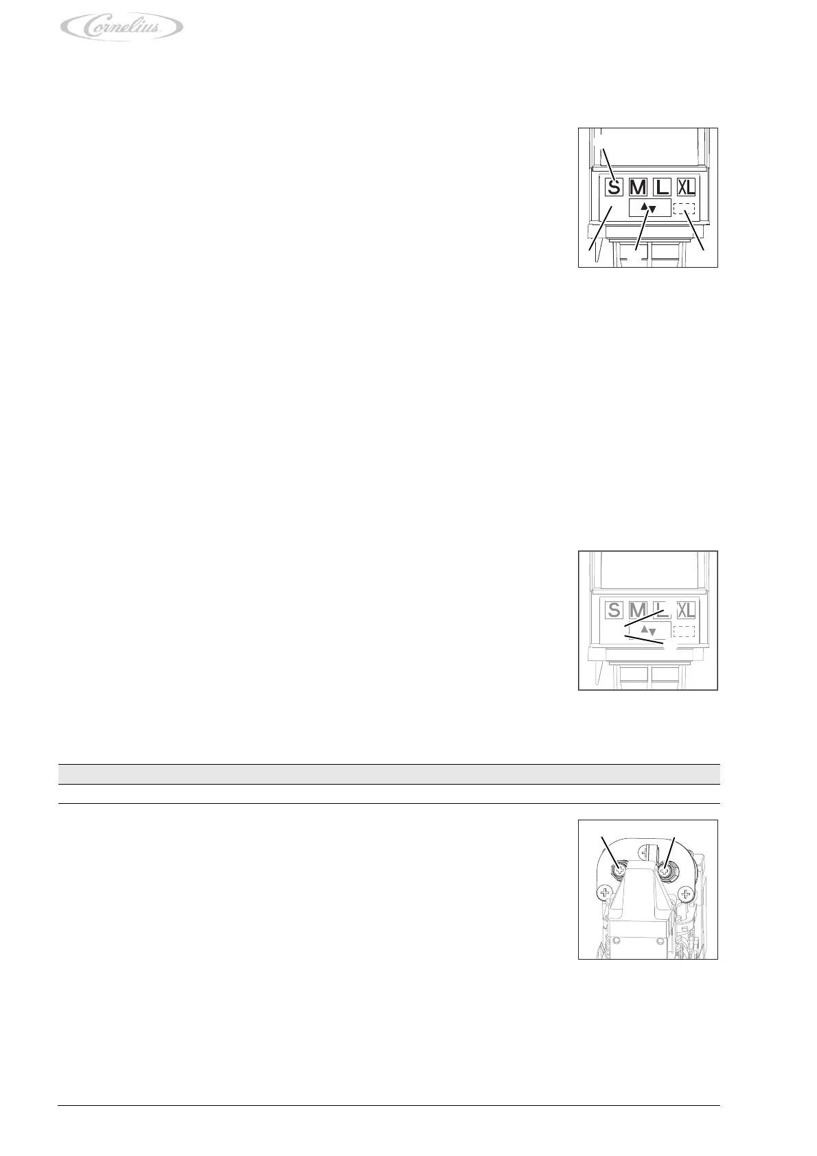
1. Set the amount of carbonated water to the required flow rate.
2. To increase the flow rate, turn the flow valve (Fig. 43/1) 1/4 turn clockwise.
3. Set the amount of syrup to the required flow rate.
4. To increase the flow rate, turn the flow valve (Fig. 43/2) 1/4 turn anti-clockwise.
Finishing tasks
1. Mount the rear valve cover, see chapter 6.2.
Fig. 43