14
2.6 Schematic Diagram and Circuit Design
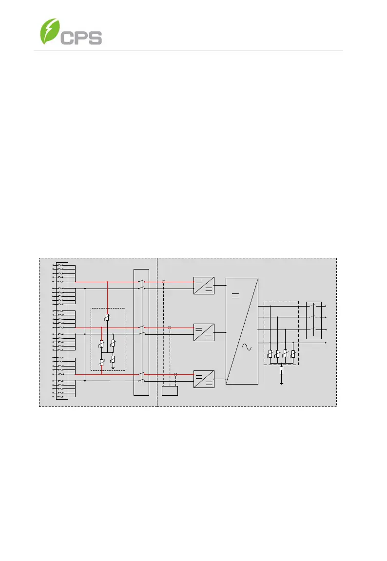
The basic electrical schematic diagram of the CPS SCA50KTL-DO/US-480
and SCA60KTL-DO/US-480 3-Phase String Inverters are shown in Figure 2-
3 and Figure 2-4. The input from PV source circuits passes through surge
protection circuitry, DC EMI wave filters, and independent DC-DC boost
circuitry to achieve maximum power point tracking and boost the voltages to
a common DC bus. The inverter uses line voltage and frequency
measurements to synchronize to the grid and converts the available PV
energy to AC power by injecting balanced 3-phase AC current into the electric
utility grid. Any high frequency AC component is removed by passing through
a two-stage relay and EMI wave filter to produce high quality AC power.
WIRE BOX INVERTER POWER HEAD
L1
L2
L3
N
PV1+
PV1+
PV1+
PV1+
PV1+
PV1-
PV1-
PV1-
PV1-
PV1-
MPPT1
MPPT2
AC
Output
PV Input
PV2+
PV2+
PV2+
PV2+
PV2+
PV2-
PV2-
PV2-
PV2-
PV2-
AC
Switch
Fuses
MPPT3
PV3+
PV3+
PV3+
PV3+
PV3+
PV3-
PV3-
PV3-
PV3-
PV3-
DC SPD
PV1+
DC Switch
Three
level
inverter
AFD
PV2+
PV3+
PV-
PE
Type Ⅲ MOV
Figure 2-3 CPS SCA50/60KTL-DO/US-480 Inverter Schematic, Standard Wirebox
The Rapid Shutdown wirebox has been designed specifically for
2017/202 NEC Rapid Shutdown applications. This wirebox includes a
powerline communications transmitter for compatibility with either Tigo TS4-
F and TS4-A-F or APsmart RSD-S-PLC rapid shutdown MLPE devices,
powered by AC at the inverter output. This PLC transmitter sends a “keep