62
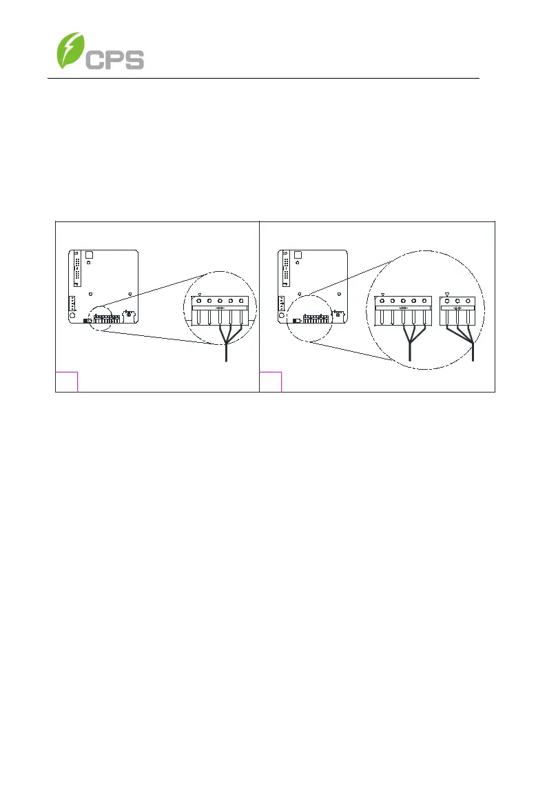
RS485 communication cables are connected via the 5-pin connector to
the port labeled (2) in Figure 3-33. When creating a network of multiple
inverters, the cables are terminated to the same 5-pin connector and 3-
pin connector. Figure 3-34 shows a single inverter communication
connection in (1) and a network configuration in (2).
RS485+
RS485-
GND
RS485 1
1
2
OFF
ON
+12V
12VGND
RS485_B-
RS485_A+
485_GND
+12V
12VGND
RS485_B-
RS485_A+
RS485_GND
RS485_GND
RS485_A+
RS485_B-
P9
P6
P7
P8
S1
P1
12VGND
+12V
RS485_A+
RS485_B-
RS485_GND
OFF
ON
+12V
12VGND
RS485_B-
RS485_A+
485_GND
+12V
12VGND
RS485_B-
RS485_A+
RS485_GND
RS485_GND
RS485_A+
RS485_B-
P9
P6
P7
P8
S1
P1
12VGND
+12V
P9
RS485 1
RS485 2
P7
P7
RS485_A+
RS485_B-
RS485_GND
Figure 3-33 RS485 Connection of Communications Board
3.4.3 RS485 Network Set-up
When the inverters are monitored via the RS485 communication, a unique
RS485 address for each inverter can be set up through the LCD interface.
Up to 32 inverters can be connected in the RS485 communication
network. The daisy-chain topology is recommended for the RS485
network connection to minimize noise and bus reflections, as shown in
Figure 3-35. Other communication topologies, such as the star networks,
are not recommended. All RS485 connections must be terminated in a
serial fashion and not to exceed 32 in total.



 To Next Page