EasyManuals Logo

Creality CR-10 S5 Complete Setup Guide

Creality CR-10 S5
23 pages
To Next Page IconTo Next Page
To Previous Page IconTo Previous Page
Page #15 background imageLoading...
Page #15 background image
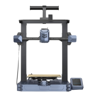
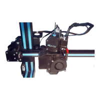
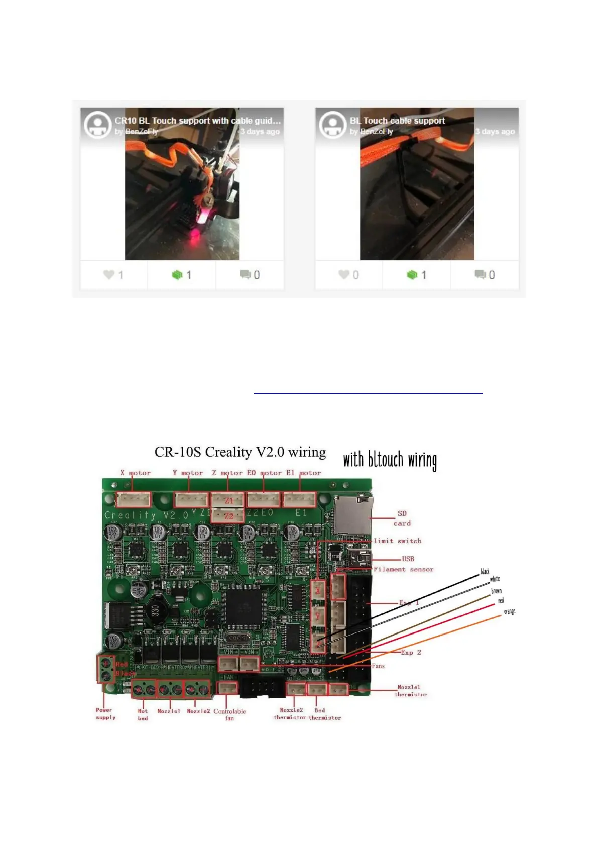
On the pictures the BLTouch cable tube is the one in orange while the stock cable is
the black one.
Next step is to plug the probe to the motherboard. There is ample documentation
online for both probes, including many warning notices related to the proper testing
of the probe ABOVE the glass plate and avoiding at any cost a crash of the print
head on the glass.
A good guide is to be found here: https://www.thingiverse.com/thing:2975949
which includes this wiring image:
PLEASE PAY PARTICULAR ATTENTION TO PLUGGING THE RED AND BROWN
WIRES AT THEIR RIGHT PLACE BECAUSE THE BLTOUCH PROBE MAY BE

Other manuals for Creality CR-10 S5

Questions and Answers:

Question and Answer IconNeed help?

Do you have a question about the Creality CR-10 S5 and is the answer not in the manual?

Creality CR-10 S5 Specifications

General IconGeneral
Build Volume500 x 500 x 500 mm
Layer Resolution0.1-0.4 mm
Printing SpeedUp to 200 mm/s
Filament Diameter1.75 mm
ConnectivitySD card, USB
Frame MaterialAluminum
DisplayLCD screen
Printing TechnologyFDM (Fused Deposition Modeling)
Heated BedYes
Bed TemperatureUp to 100°C
Nozzle TemperatureUp to 250°C
File FormatSTL, OBJ, G-code
Nozzle Diameter0.4 mm
Supported FilamentsPLA, ABS, TPU
Power SupplyAC 110-220V

Related product manuals