2-15 Installation
2.11 Program Input Fault Time-out
You can enable an automatic turn-off of the carrier in the event of program failure. To enable
this option, see remote I/O connector pin out chart on page 2-16. The time between program
failure and carrier turn-off is set by a jumper (JP1) on the Driver Switch Logic board. (See
page 6–3 for board location.) Jumper pins 1 and 2 (the two pins closest to the edge of the
board) for a delay of approximately 30 seconds; pins 3 and 4 for a 2 minute delay; pins 5 and 6
for a 4 minute delay, and pins 7 and 8 for an 8 minute delay. Placing a jumper on pins 9 and
10 will disable the time-out timer.
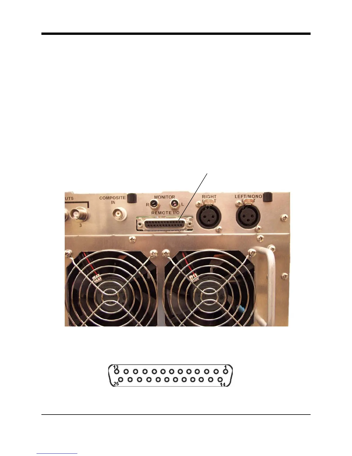
2.12 Remote I/O Connector
Remote control and remote metering of the transmitter is made possible through a 25 pin, D-
sub connector on the rear panel. (No connections are required for normal operation.)
Remote I/O Connector
Illustration 2–17 Remote I/O Connector
Illustration 2–18 Remote I/O Connector (DB-25 Female)