4.12 Receiver Circuit Board Option
This option allows the transmitter to be used as a translator. The receiver board receives ter-
restrially fed RF signal and converts it to composite audio which is then fed into the exciter
board. Microprocessor controlled phase lock loop technology ensures the received frequency
will not drift, and multiple IF stages ensure high adjacent channel rejection. Refer to Illustra-
tions 4–6, 6–16 and its schematic for the following discussion.
The square shaped metal can located on the left side of the receiver board is the tuner module.
The incoming RF signal enters through the BNC connector (top left corner) and is tuned
through the tuner module. Input attenuation is possible with the jumper labeled “LO” “DX”, on
the top left corner of the receiver board. Very strong signals can be attenuated 20 dB auto-
matically by placing the jumper on the left two pins (“LO” position). An additional 20 dB at-
tenuation is also available with the jumpers in the top left corner of the board. The frequencies
are tuned by setting switches SW1 and SW2 (upper right corner). These two switches are
read upon power up (or by momentarily shorting J7) by the microprocessor (U4). The micro-
processor then tunes the tuner module to the selected frequency. The frequency range is 87.9
Mhz at setting “00” to 107.9 Mhz at setting “64”. Other custom ranges are available.
Located in the lower left-hand corner of the Receiver Module is a 3.5mm headphone jack. De-
modulated Left and Right audio is present at this jack. A regular pair of 32 ohm stereo head-
phones, such as the types used with portable audio devices, can be used to monitor the audio
on the receiver module.
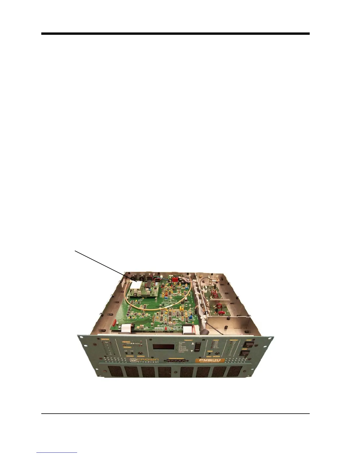
Illustration 4–9 Receiver Module
Receiver
Module
4-16 FM600 User’s Manual