4.2 Audio Processor/Stereo Generator Circuit Board
The audio board provides the control functions of audio processing-compression, limiting, and
expansion, as well as stereo phase-error detection, pre-emphasis and generation of the com-
posite stereo signal.
Illustration 6-4 and accompanying schematic may be useful to you during this discussion. The
overall schematic for the audio board is divided into two sheets; one each for the processor
and stereo generator sections of the board.
Reference numbers are for the left channel. Where there is a right-channel counterpart, refer-
ence number are in parenthesis.
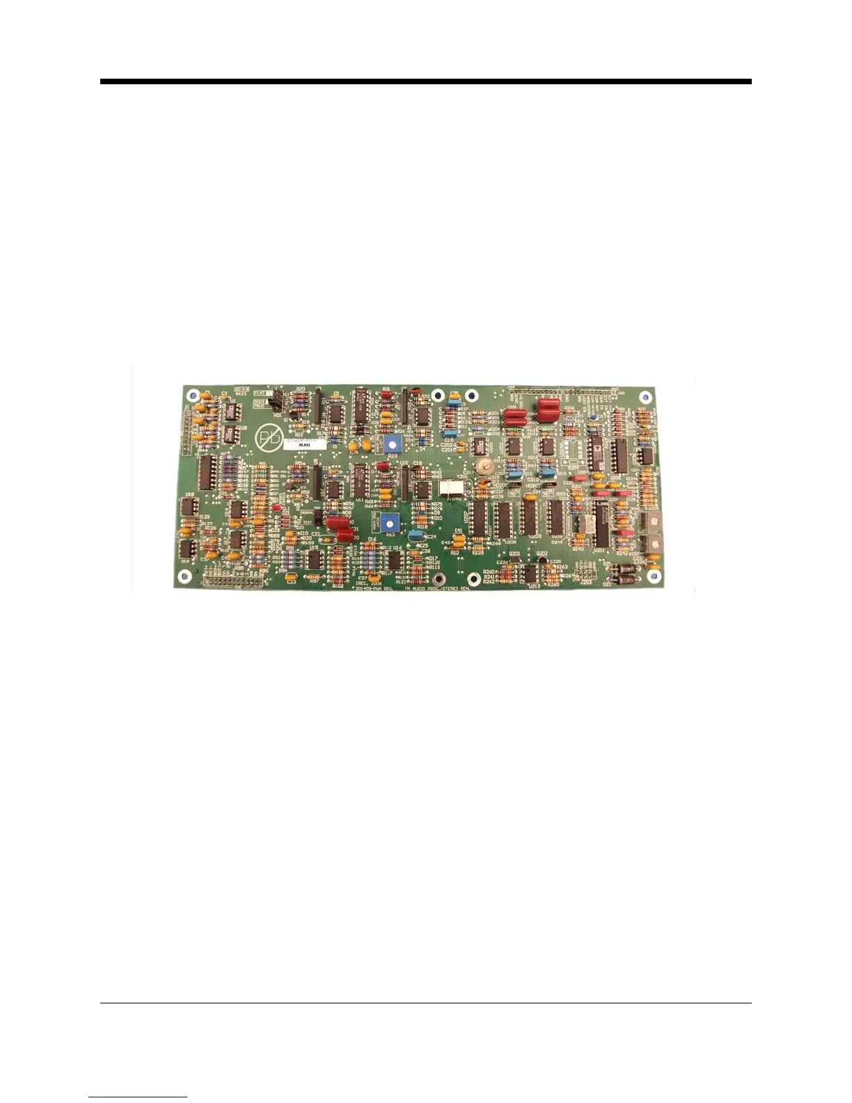
Illustration 4–2 Audio Processor/Stereo Generator Board
4.2.1 Audio Processor Section
Audio input from the XLR connector on the rear panel of the transmitter goes to instrument am-
plifier, U2 (U8). Two-bit binary data on the +6 dB and +12 dB control lines sets the gain of U2
(U8) to one of four levels in 6-dB steps. Gain of U2 is determined by R5, R6, or R7 (R45, R46,
or R47) as selected by analog switch U1.
U3 (U9) is a THAT2180 voltage-controlled amplifier with a control-voltage-to-gain constant of
6.1 mV/dB. The 2180 is a current-in/current-out device, so signal voltages at the input and out-
put will be zero. R11 converts the audio voltage at the output of U2 (U8) to current at the input
of U3 (U9). U3 (U9) output current is converted to audio voltage by U4A (U10A).
U4B (U10B) is a unity-gain inverter. When the positive peaks at the output of U4A (U10A) or
U4B (U10B) exceeds the gain-reduction threshold, U15 generates a 0.25 Volts-per-dB DC con-
trol bias, producing wide-band gain reduction for U3 (U9). The dB-linear allows a front-panel
display of gain control on a linear scale with even distribution of dB.
4-3 Principles of Operation