4.4 Metering Circuit
The ALC and metering circuitry is on the motherboard (see Illustration 6–6). This circuit proc-
esses information for the RF and DC metering, and produces ALC (RF level-control) bias. It
also provides reference and input voltages for the digital panel meter, voltages for remote me-
tering, and drive for the front-panel fault indicators.
Illustration 6–6 and accompanying schematics complement this discussion.
PA voltage and current come from a metering shunt on the Driver Switch Logic board. The
PAI input is a current proportional to PA current; R153 converts the current to voltage used for
metering and control. A voltage divider from the PAV line is used for DC voltage metering.
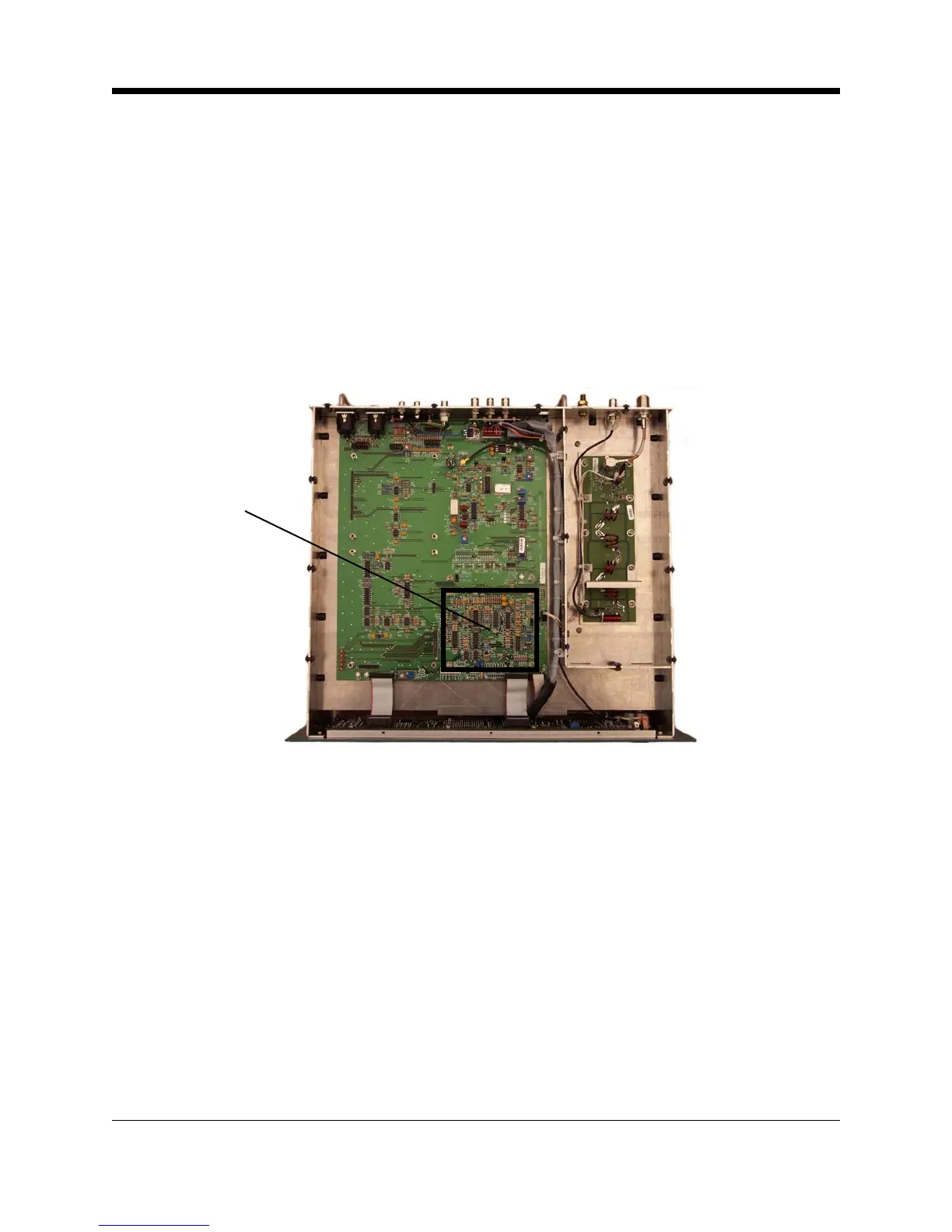
Illustration 4–4 Motherboard (Metering Circuits)
U23A, U23B, and U24A, with their respective diodes, are diode linearity correction circuits.
Their DC inputs come from diode detectors in the RF reflectometer in the RF low-pass filter
compartment.
U24B, U24C, are components of a DC squaring circuit. Since the DC output voltage of U24C is
proportional to RF voltage squared, it is also proportional to RF power.
U22C, U22A, U20A, and U22D are level sensors for RF power, reflected RF power, PA tem-
perature, and external PA current, respectively. When either of these parameters exceeds the
limits, the output of U22B will be forced low, reducing the ALC (RF level control) voltage,
which, in turn, reduces the PA supply voltage.
The DC voltage set point for U22A (reflected RF voltage) is one-fifth that of U22C (forward RF
voltage). This ratio corresponds to an SWR of 1.5:1 [(1+.2)/(1– .2)=1.5]. The U25 inverters
drive the front panel fault indicators.
Metering Circuits
4-7 Principles of Operation