4.9 RF Amplifier
The RF power amplifier modules are mounted on a combiner board, heat sink, slide rail as-
sembly which slides into the main chassis at the rear, and is fastened to the back panel with
six screws. RF power, DC power, and control voltages enter the PA assembly through a 72-pin
edge connector that slides into at the front of the chassis.
The amplifier is built around two SD2942, dual power MOSFET’s rated for 50 volts DC and a
maximum power of about 350 watts. When biased for class B, the transistor has a power gain
of 20dB. The RF power amplifier is biased below class B in the transmitter.
Input transformer, T1111, is made up of two printed circuit boards. The four-turn primary board
is separated from the one-turn secondary by a thin dielectric film. R1112-R1117 are for damp-
ing. Trim pot R1111 sets the bias.
Output transformer, T1121, has a one-turn primary on top of the circuit board and a two-turn
secondary underneath. Inductors L1121 and L1122 provide power line filtering.
The amplifiers are surrounded by a 50 Ohm impedance, input/output combiner board which
takes 15 watts input and divides it equally to each power amp. Then the output from each am-
plifier is combined to for a single output.
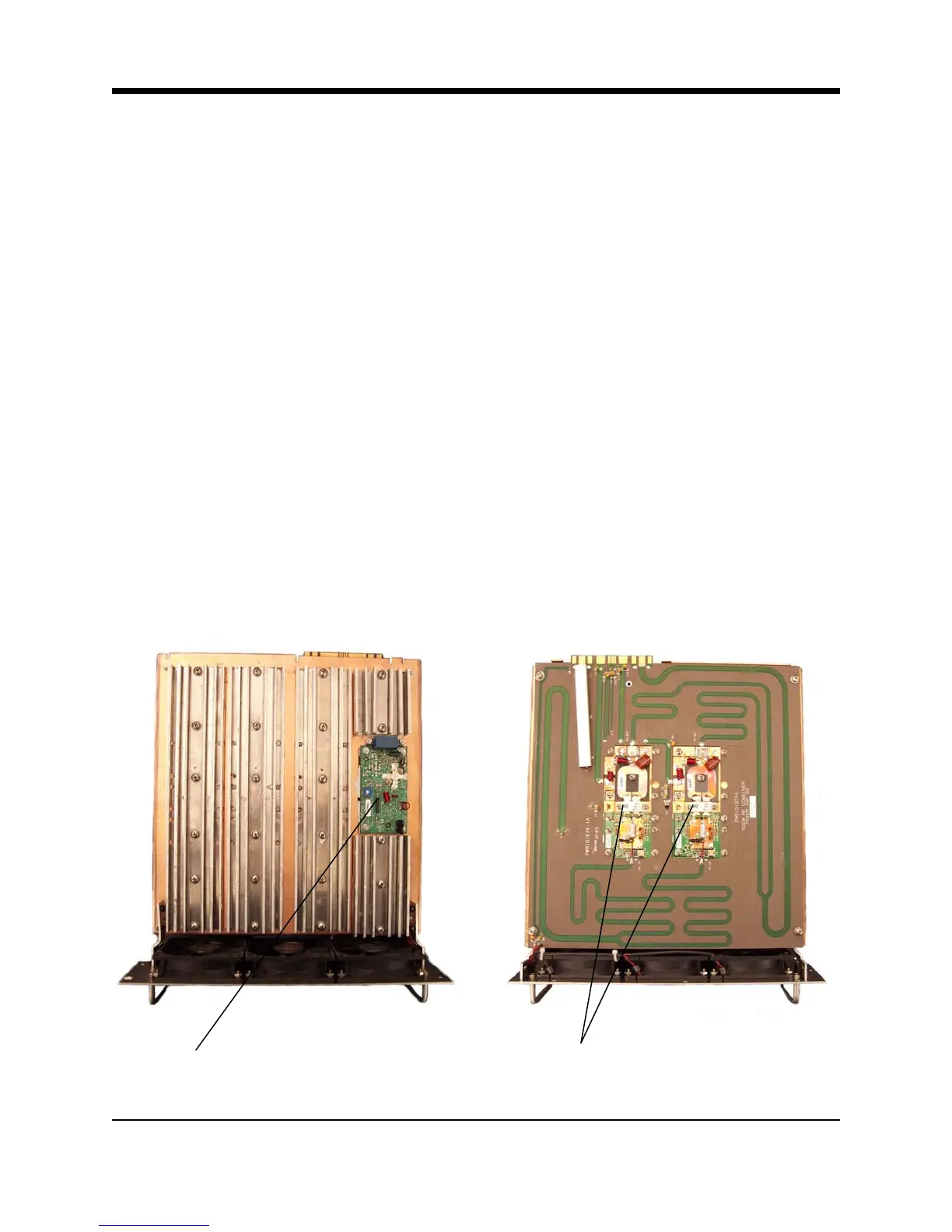
RF Driver
Amplifier
RF Power
Amplifiers
Illustration 4–7 RF Power Amplifier Module
4-14 FM600 User’s Manual