4.3 RF Exciter Circuit
This circuit is also known as the Frequency Synthesizer. The Frequency Synthesizer part of
the motherboard is no longer a separate module as was the case on older transmitters. The
entire component side of the motherboard is a ground plane. Frequency selector switches
located on the front panel of the transmitter establish the operating frequency. The VCO
(voltage-controlled oscillator) circuitry is inside an aluminum case.
Illustration 6-6 and accompanying schematics can be used as reference in this
discussion.
VCO1 operates at the synthesizer output frequency of 87 MHz to 108 MHz.
The frequency is controlled by a voltage applied to pin 8 of the VCO. A sample of the RF
comes from A2 and is fed to the PLL chip U13. U13 is a phase-locked-loop frequency synthe-
sizer IC. The 10.24 MHz from the crystal oscillator is divided to 10 kHz. Internal programma-
ble dividers divide the 87 - 108 MHz RF to 10 kHz. Differences between the two signals pro-
duce error signals at pins 7 and 8 of U14.
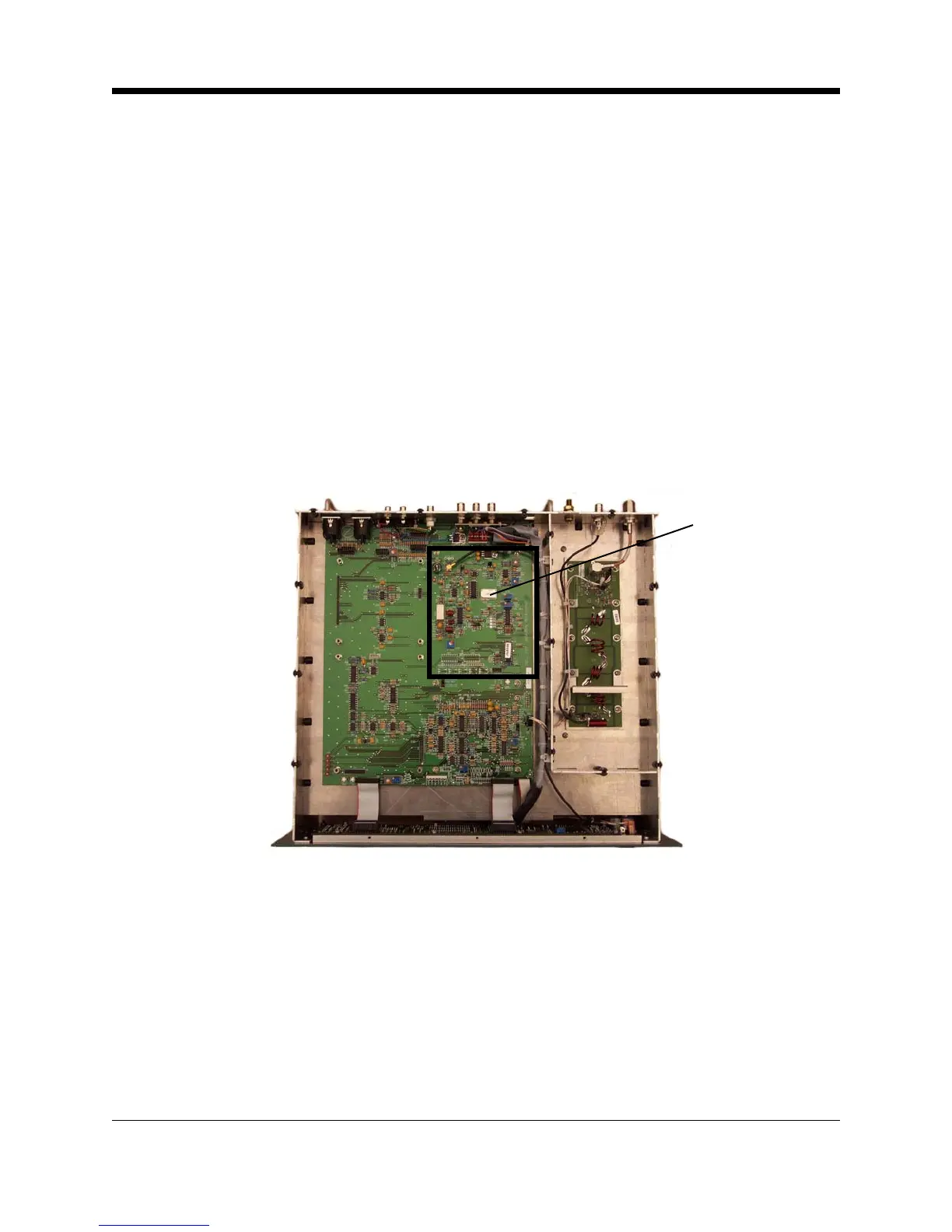
Illustration 4–3 Motherboard (Exciter Circuits)
Frequency selector switches are read by shift registers U17 and U18. Data from the shift reg-
isters is read by U16 which then programs the PLL (Phase Lock Loop) IC U13.
U14B is a differential amplifier and filter for the error signal. Audio that is out of phase with that
appearing on the error voltage is introduced by U14A, allowing for greater loop bandwidth with
less degradation of the low frequency audio response.
Lock and unlock status signals are available at the outputs of U15E and U15F respectively.
Modulation is introduced to the VCO though R72 and R122.
Exciter Circuits
4-6 FM600 User’s Manual