4.12 Receiver Circuit Board Option (Continued)
When a stereo signal is present, LED 3 illuminates which indicates that left and right audio is
available. Then the stereo signals go to gain stages and out to the RCA jacks on the back of
the cabinet. These can be used for off-air monitoring of the audio signal. Incoming frequency
can be monitored from the frequency monitor BNC jack on the back. The stereo buffer, stereo
decoder, and gain stages and have no effect on the signal that goes through the transmitter.
The power supply is fairly straight forward. The incoming 12 volt supply goes to a 7809, 9 volt
regulator (VR1) which supplies all 9–volt needs on the board. The 9 volts also supplies a
7805, 5 volt regulator (VR2) which supplies all 5–volt needs on the board. Plus and minus 12
volts from the motherboard is filtered and supplies various needs on the board. Finally there is
a precision reference voltage. Two 2.5 volt reference shunts act very much like a very accu-
rate zener diode to provide a precision 5 volt supply to the metering board.
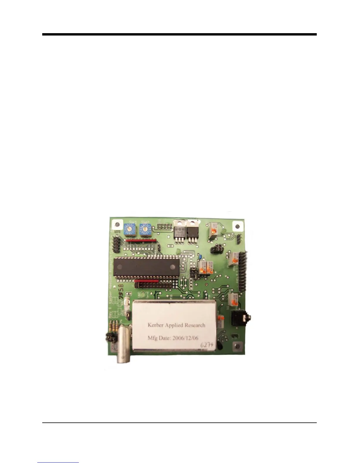
Illustration 4–10 Receiver Module
4-17 Principles of Operation