CSL CS468 16-Port EPC CLASS 1 GEN 2 RFID READER
USER'S MANUAL, VERSION 2.0.1
Copyright © Convergence Systems Limited, All Rights Reserved
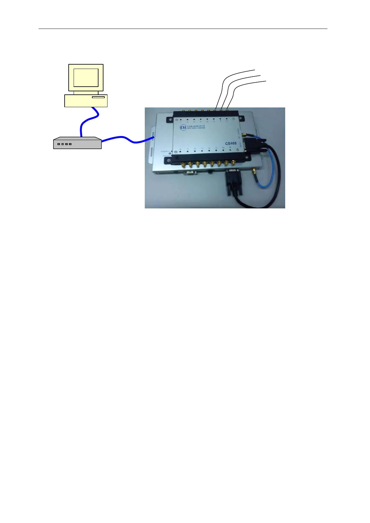
For PoE power supply mode, the connection diagram is as below:
Figure 4-7 POE adaptor Setup
The reader is connected to a PoE-enabled switch or a PoE adaptor’s output port. The input port
of PoE adaptor is connected to a host computer.
PoE-enabled
Network Switch