TRANSMISSION SYSTEM
4-15
D569-W02 May-2003
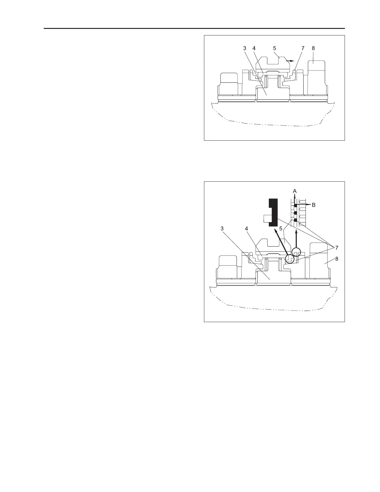
First Stage
An effort to place the main gear shift lever to the 3rd or
4th speed causes the shifter (5) and synchronizer keys
(4) to move slightly.
Then, the end surface of the synchronizer key (4)
presses the synchronizer ring (7) against the cone-
shaped portion of the gear (8). The frictional force gen-
erated at the cone-shaped portion rotates the synchro-
nizer ring (7), synchronizer keys (4) and hub (3) which
is splined to the counter shaft.
(3) Hub (7) Synchronizer Ring
(4) Synchronizer Key (8) Gear
(5) Shifter
569W411A
Second Stage
When the synchronizer keys (4) are prevented by the
synchronizer ring (7) from sliding.
The synchronizer keys (4) are disengaged from the
shifter (5).
The synchronizer keys (4) go into the grooves provided
in the synchronizer ring (7).
However, since the width of the grooves is wider than
that of the keys, the synchronizer keys begin rotating at
the same speed with the shifter (5) and hub (3) with a
time lag.
In the meantime, the shifter (5) in its sliding direction
and the synchronizer ring (7) in its rotating direction
press each other at their chamfered portions to syn-
chronizer ring (7) with that of the gear (8).
(3) Hub (7) Synchronizer Ring
(4) Synchronizer Key (8) Gear
(5) Shifter
569W412A
www.mymowerparts.com
K&T Saw Shop 606-678-9623 or 606-561-4983

 Loading...