HYDRAULIC SYSTEM
6-77
D569-W02 May-2003
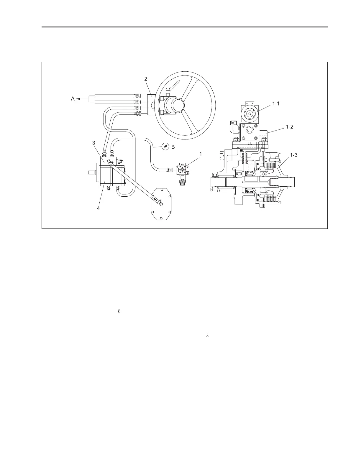
6.3 PTO SYSTEM
A. SCHEMATIC DIAGRAM OF PTO SYSTEM
(1) PTO Clutch Valve
(1-1) Solenoid Valve Ass’y
(1-2) Modulator Valve Ass’y
(1-3) PTO Clutch Ass’y
B. PRINCIPLES OF OPERATION
PTO operates the steering device and PTO clutch at
the hydraulic pump 2 and the oil flows to the prior valve
from hydraulic hose T line connected with orbitrol unit
T port and the flow rate of 7
/min operates solenoid
valve (1-1), modulator valve (1-2), PTO clutch (1-3). At
this time, PTO clutch operation shall be controlled by
electrical device of PTO ON-OFF switch.
(2) Orbitrol Unit
(3) Prior Valve Ass’y
(4) Gear Pump Ass’y
C. DESCRIPTION OF COMPONENTS
1) Solenoid valve assembly: to control the oil path by
ON-OFF electrically.
2) Modulator valve assembly: to generate the regular
pressure (16 kg/cm
2
~ 18 kg/cm
2
) to operate the
PTO clutch.
3) Prior valve assembly: to deliver the regular flow rate
7 (
/min ) to operate PTO.
4) PTO clutch assembly: to transmit the power to the
PTO axle by the operation of piston inside the clutch
assembly.
569W6A6A
(A) Steering Cylinder
(B) Pressure Gauge
www.mymowerparts.com
K&T Saw Shop 606-678-9623 or 606-561-4983

 Loading...