ENGINE
2-17
D569-W02 May-2003
569W231A
569W232A
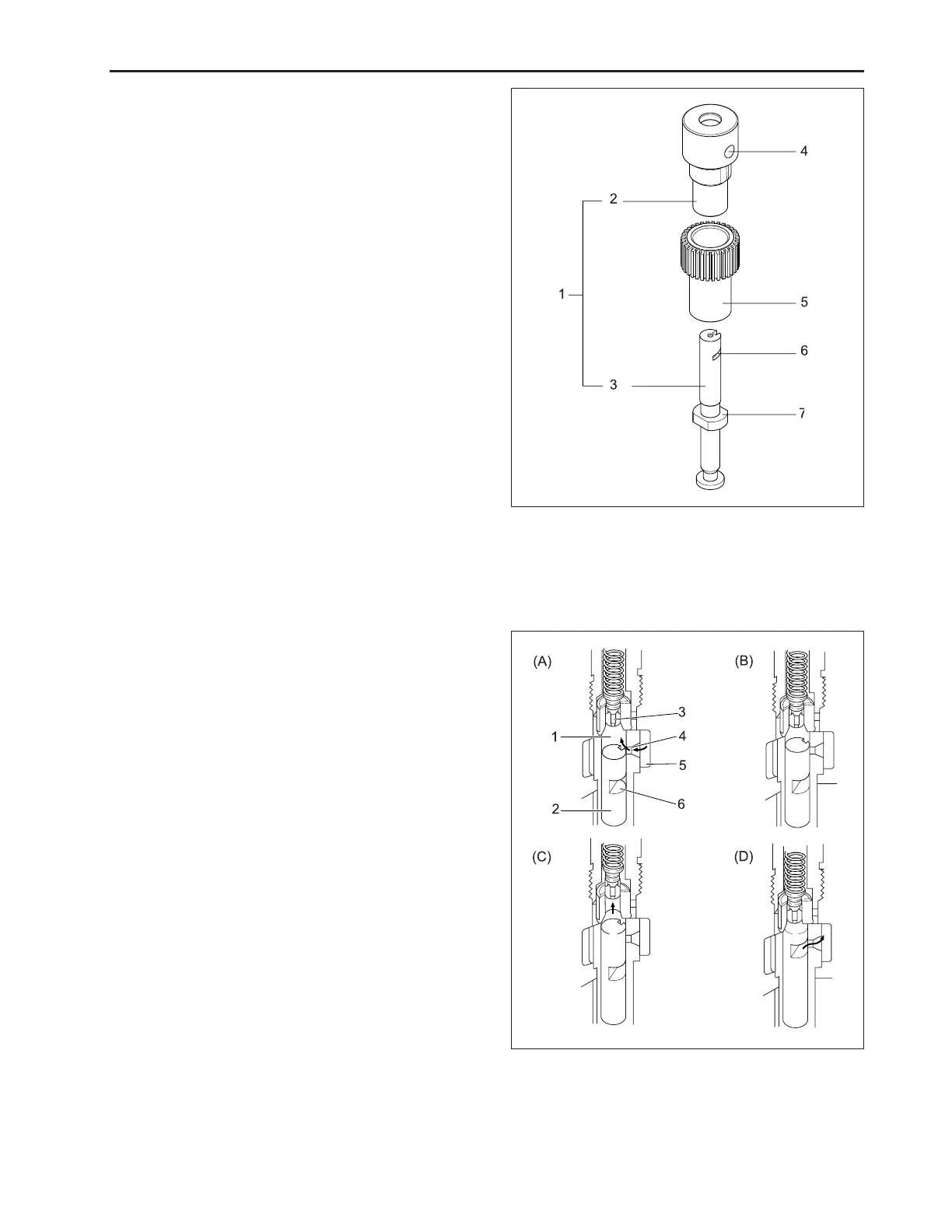
(1) Pump Element (5) Control Sleeve
(2) Cylinder (6) Control Groove
(3) Plunger (7) Driving Surface
(4) Feed Hole
(1) Delivery Chamber (4) Feed Hole
(2) Plunger (5) Fuel Chamber
(3) Delivery Valve (6) Control Groove
b. Operation of Pump Element
(A) Before delivery
As the taper lowers, the plunger (2) lowers and fuel is
drawn into the delivery chamber (1) through the feed
hole (4) from the fuel chamber (5).
(B) Beginning of delivery
When the plunger is pushed up by the cam and the
head of the plunger closes the feed hole (4), the pres-
sure in the delivery chamber (1) rises to push the deliv-
ery valve (3) open.
(C) Delivery
While the plunger (2) is rising, delivery of fuel continues.
(D) End of delivery
When the plunger rises further and the control groove
(6) on its periphery meets the feed hole, the fuel re-
turns to the fuel chamber (5) from the delivery chamber
(1) through the control groove (6) and the feed hole (4).
a. Pump Element
The pump element (1) consists of a plunger (3) and
cylinder (2), their sliding surfaces are precision ma-
chined to maintain fuel tightness. The plunger (3) fits
in the control sleeve (5) at the driving surface (7). The
sleeve is engaged with the control rack, which rotate
the plunger in the cylinder to control the amount of fuel
delivery.
www.mymowerparts.com
K&T Saw Shop 606-678-9623 or 606-561-4983

 Loading...