DGS-3200 Series Layer 2 Gigabit Ethernet Managed Switch
108
Bandwidth Control
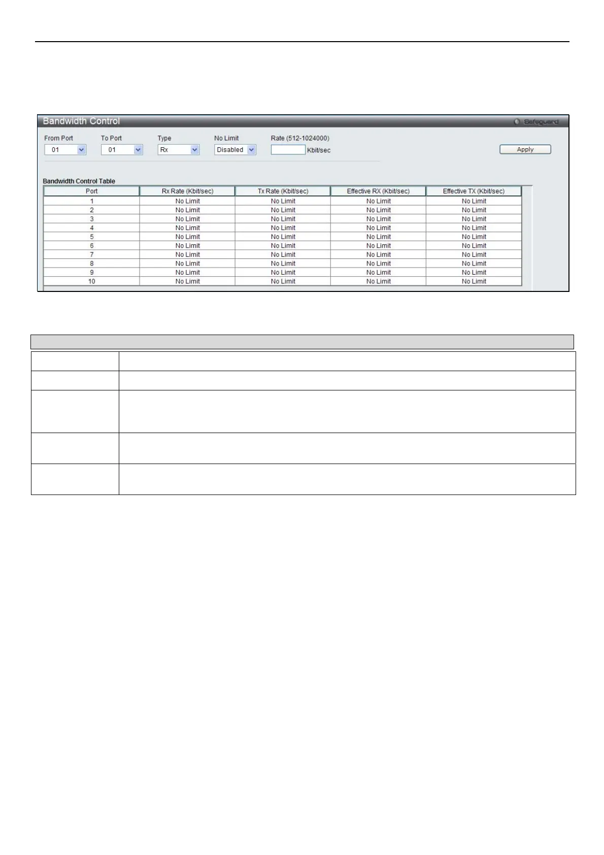
The bandwidth control settings are used to place a ceiling on the transmitting and receiving data rates for any selected port. In the
QoS folder, click Bandwidth Control, to view the window shown below.
Figure 8- 2. Bandwidth Control window
The following parameters can be set or are displayed:
Parameter Description
From Port
The beginning port of a consecutive group of ports to be configured.
To Port
The ending port of a consecutive group of ports to be configured.
Type
This drop-down menu allows a selection between RX (receive), TX (transmit), and Both. This
setting will determine whether the bandwidth ceiling is applied to receiving, transmitting, or both
receiving and transmitting packets.
No Limit
This drop-down menu allows the user to specify that the selected port will have no bandwidth limit.
Enabled disables the limit.
Rate
This field allows the input of the data rate that will be the limit for the selected port. The user may
choose a rate between 512 and 1024000 Kbits per second.
Click Apply to set the bandwidth control for the selected ports. Results of configured Bandwidth Settings are displayed in the
Bandwidth Control Table at the bottom of the window.
Traffic Control
On a computer network, packets such as Multicast packets and Broadcast packets continually flood the network as normal
procedure. At times, this traffic may increase do to a malicious endstation on the network or a malfunctioning device, such as a
faulty network card. Thus, switch throughput problems will arise and consequently affect the overall performance of the switch
network. To help rectify this packet storm, the Switch will monitor and control the situation.
Packet storms are monitored to determine if too many packets are flooding the network based on threshold levels provided by the
user. Once a packet storm has been detected, the Switch will drop packets coming into the Switch until the storm has subsided.
This method can be utilized by selecting the Drop option of the Action parameter in the window below.
The Switch will also scan and monitor packets coming into the Switch by monitoring the Switch’s chip counter. This method is
only viable for Broadcast and Multicast storms because the chip only has counters for these two types of packets. Once a storm
has been detected (that is, once the packet threshold set below has been exceeded), the Switch will shut down the port to all
incoming traffic, with the exception of STP BPDU packets, for a time period specified using the Count Down parameter.
If a Time Interval parameter times-out for a port configured for traffic control and a packet storm continues, that port will be
placed in Shutdown Forever mode, which will cause a warning message to be sent to the Trap Receiver. Once in Shutdown
Forever mode, the only method of recovering the port is to manually recoup it using the Port Settings window in the
Configuration folder. Select the disabled port and return its State to Enabled status. To utilize this method of Storm Control,
choose the Shutdown option of the Action parameter in the window below.
 Loading...