©
200416 3-1
CE engine inlet/exhaust system
TECHNICAL DATA
ΧΦ65/75/85 series
4
0
3. CE ENGINE INLET/EXHAUST SYSTEM
3.1 GENERAL
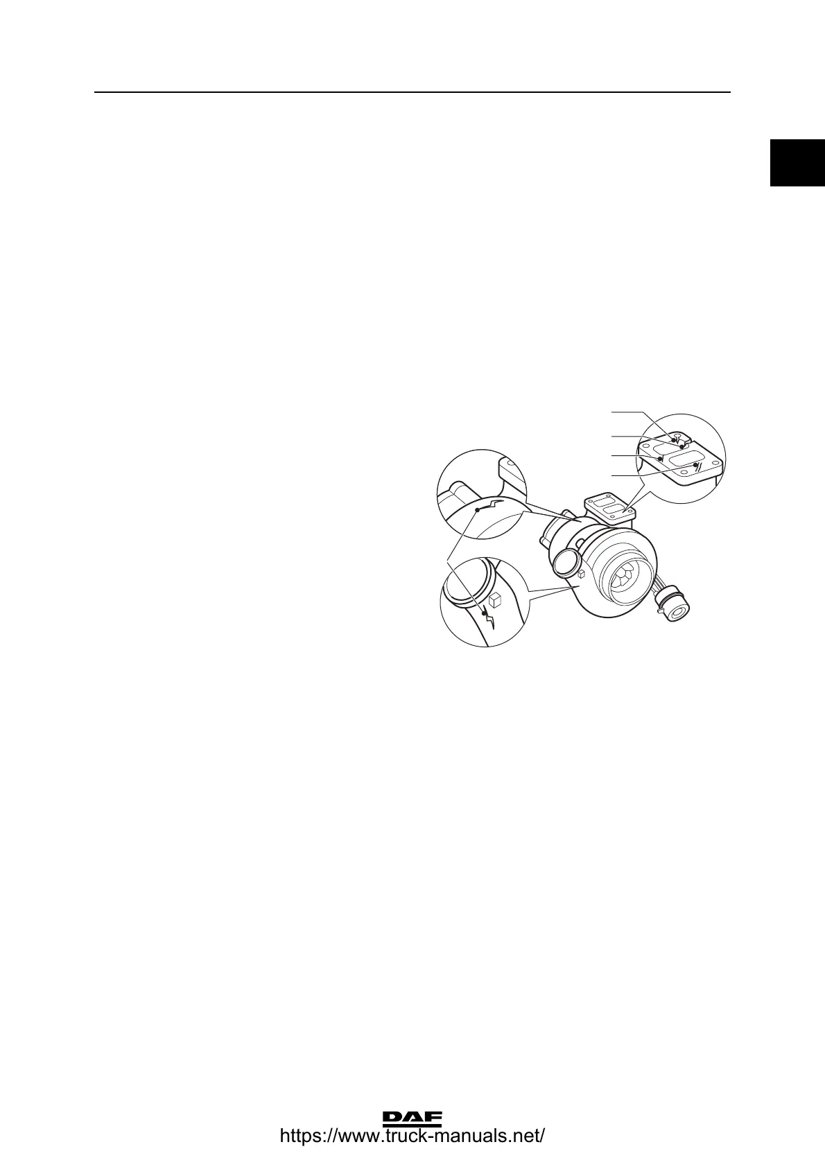
Turbocharger
Rejection standards for cracking
1. Cracks in the connector flange must not
reach as far as the attachment holes.
2. Cracks in the connector flange must not
reach from the channels as far as the
exterior.
3. Cracks in the connector flange may not be
longer than 15 mm.
4. Cracks in the connector flange must not be
less than 6 mm apart.
5. There must be no cracks in the housing.
Exhaust gas back pressure
Inlet underpressure
Glow element
CE 136 C Holset HY 35 W
CE 162 C Holset HY 35 W
CE 184 C Holset HX 35 W
Minimum actuating pressure of wastegate cap-
sule under which the control rod will move 2.0 bar
Axial bearing play of compressor shaft 0.038 - 0.093 mm
Radial bearing play of compressor shaft 0.329 - 0.501 mm
1
2
5
3
4
i400784
At full-load engine speed 100 mbar
Maximum back pressure during engine brake ap-
plication 4.3 bar
At full-load engine speed (clean air filter) 25 mbar
At full-load engine speed (clogged air filter) 62 mbar
Resistance value 180 - 220 m
https://www.truck-manuals.net/
 Loading...