146
8
Disassembling Procedure
Work Procedure Point
WARNING
Before disassembling work, be sure
to turn OFF all power supplies.
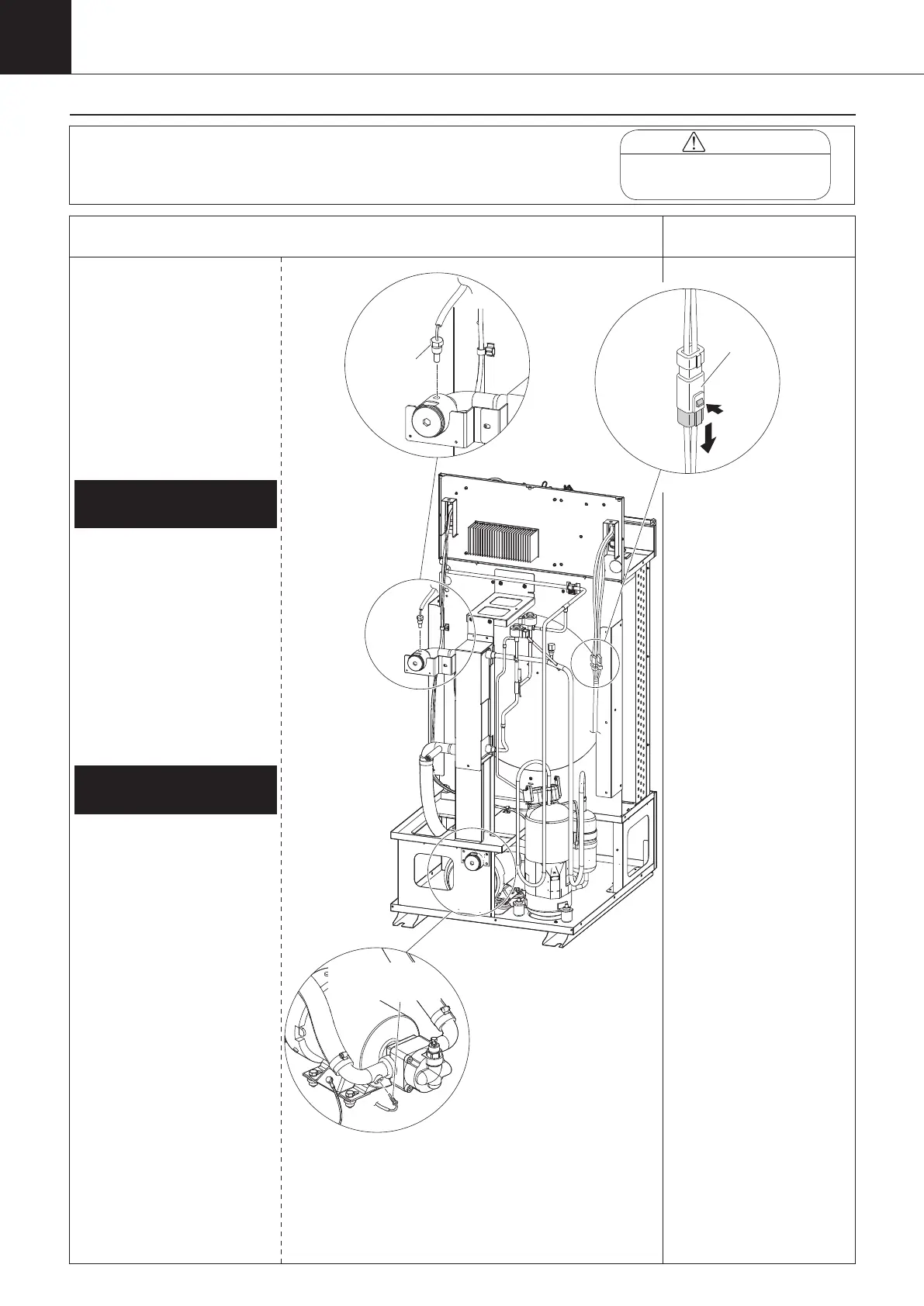
Procedure for Removing
Thermistors (1/2)
*1
1 Remove the switch box
cover, top panel, back
panel, left side panel,
and right side panel
in accordance with
“Procedure for Removing
Outside Panel Block
(P.133)”.
① Disconnect the relay
connector of the outlet
oil thermistor. (wire
color: blue) Remove the
band banding the outlet
oil thermistor in the oil
cooling unit.
② Remove the outlet oil
thermistor with a wrench.
① Disconnect the relay
connector of the inlet oil
thermistor. (wire color:
yellow) Remove the
band banding the inlet
oil thermistor in the oil
cooling unit.
② Remove the inlet oil
thermistor with a wrench.
1.
Removing outlet oil
thermistor (Th-2)
2.
Removing inlet oil
thermistor (Th-4)
*1
Disconnect the relay
connector in the oil cooling
unit before replacing the
thermistors.
Outlet oil
thermistor
(Th-2)
Relay
connector
Inlet oil
thermistor (Th-4)
00_PB00540A_M10.indb 146 2023/08/09 12:59:24