3030
trouBleShootIng
network trouBleShootIng
Communication is achieved by taking the difference between
a positive dc signal and a negative dc signal. The positive dc
signal is termed “data 1” or “1”. Data 1 is positive with respect
to ground (or common). The negative dc signal is termed
“data 2” or “2”. Data 2 is negative with respect to ground (or
common).
Data 1 should be approximately 2.8 volts dc. Data 2 should
be approximately 2.2 volts dc. The voltage difference between
data 1 and data 2 should be approximately 0.6 volts dc.
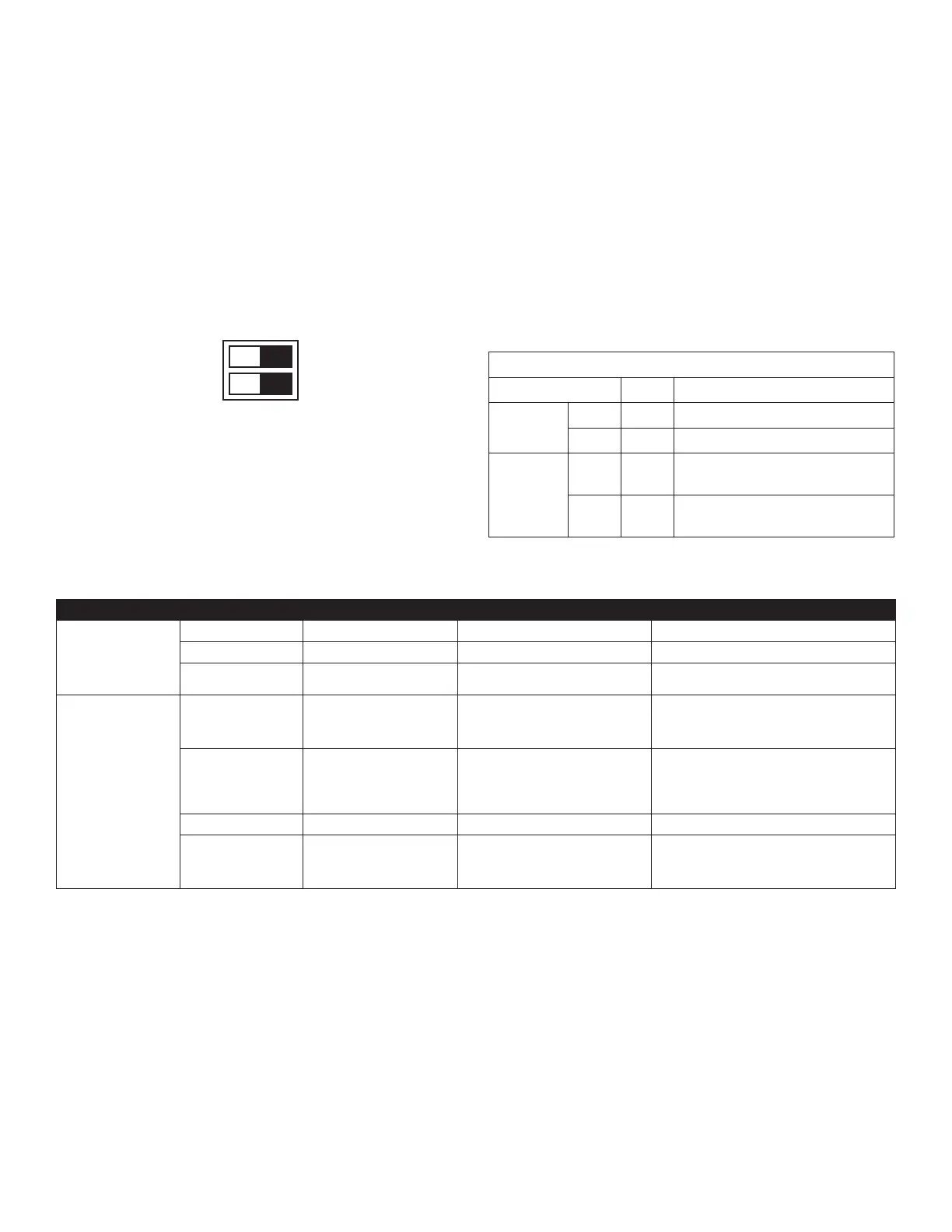
Verify that the bus DS1 dip switches are in the ON position.
OFF ON
1
TERM
2
This heat pump is a fully communicating system, constituting
a network. Occasionally the need to troubleshoot the network
may arise. The integrated control module has some onboard
tools that can be used to troubleshoot the network. These
tools are: red communications LED, green receive (Rx) LED,
and the learn button.
• Red communications LED – Indicates the status of the
network. The table below indicates the LED status and
the corresponding potential problem.
• Green receive LED – Indicates network trafc. The table
below indicates the LED status and the corresponding
potential problem.
• LEARN button – Used to reset the network. Depress the
button for approximately 5 seconds to reset the network.
Dipswitch Default Factory Settings
Switch # Setting Purpose
OD DS1
1 ON CT Communication Enabled
2 ON CT Communication Enabled
OD DS2
1 OFF
Cooling Emergency Mode for
Future Use*
2 OFF
Cooling Emergency Mode for
Future Use*
*OD DS2 switch 1 and 2 both must be turned off during normal
operation mode
LED COLOR LED Status Indication Probable Causes Corrective Actions
Red Communications LED
(H1P)
Off Nominal condition • None • None
1 Flash Communications Failure • Unknown packet is received • Depress learn button
2 Flash Out-of-box reset
• Control power up
• Learn button depressed
• None
Green Receive LED (H2P)
Off
No power
Communications error
• No power to Outdoor unit
• Open fuse
• Communication error
• Check circuit breakers and fuses; Replace if needed
• Reset network by depressing learn button
• Check communication wires (data 1/ data 2 wires);
Replace if needed
1 Steady Flash No network found
• Broken/ disconnected communication
wire(s)
• Heat pump is installed as a legacy/
traditional system
• Check communication wires (data 1/ data 2 wires);
Replace if needed
• Check installation type (legacy/ traditional or com-
municating)
• Check data 1/ data 2 voltages
Rapid Flashing Nominal network trafc • Control is “talking” on network as expected • None
On Solid Data 1/Data 2 miss-wire
• Data 1 and data 2 wires reversed at indoor
unit, thermostat, or outdoor unit
• Short between data 1 and data 2 wires
• Short between data 1 or data 2 wires
• Check communication wires (data 1/ data 2 wires);
Replace if needed
• Check data 1/ data 2 voltages