SYSTEM OPERATION
12
Daikin One+ System Advanced Features
The Daikin One+ system permits access to additional system
information, advanced setup features, and advanced
disgnostic/troubleshooting features. These advanced features
are organized into a menu structure. For detailed functions
and menu layout, please visit the Daikin One+ Smart
Thermostat websire at http://www.daikinone.com. (If using a
CTK04 thermostat, please see the addendum for further
instructions.)
ERROR HISTORY
This menu provides access to the most recent faults.
The recent system error histories are displayed on the screen.
Errors are stored in order from most recent to least re-cent.
Any consecutively repeated error is stored only once.
NOTE: It is highly recommended that the error history be
cleared after performing maintenance or servicing the system.
STATUS
This menu displays information about the systems current
status.
This menu can be utilized to confirm correct functionality of
the equipment and for troubleshooting purposes.
PUMP DOWN / CHARGE MODE
This function can be enabled in this menu.
S
ET
7-S
EGMENT
M
ODE
D
ISPLAY
T
O
P
UMP
D
OWN
Please follow the following sequence to enter PUMP DOWN to
accumulate the refrigerant to outdoor unit by 7 Segment Mode.
Do not operate COOL ON mode to enter PUMP DOWN. Before
start-ing the PUMP DOWN operation, change indoor fan trim,
delay and profile back to default and stop electric heater and
gas furnace.
Remove if no trim feature. In this operation, the gas and liquid
service valve should be opened.
1. Set 7-segment display to SCREEN 4 (SETTING MODE 2) Setting
No. 8 and change the display from “-01” to “-00”. System will
then automatically start PUMP DOWN operation.
For information on how to set 7-segment display, see the
section SETTING THE MODE DISPLAY in this manual.
2. Approximately one minute later, the compressor should start
operating. Check the amperage at the compressor wiring to
see the compressor operation status. Unit display error code
E11 (System verification Test) once the PUMP DOWN
operations starts.
3. Close liquid service valve approximately two minutes after
compressor has come on.
4. Compressor will come to a stop automatically. Close the gas
service valve immediately after the compressor
stops.Aftercompletion of PUMP DOWN, unit shows error code
“E11”.
NOTE: Refrigerant cannot be collected to the outdoor unit
completely if the system is overcharged or if there is a delay in
closing the liquid service valve and gas service valve. Evacuate
the left over refrigerant from the system using a recovery
machine.
S
YSTEM
T
EST
The mandatory system verification test is enabled from this
SYSTEM TEST menu, which enables a functional check of the
equipment, in addition to ensuring proper stop valve position.
C
OOL
S
ETTINGS
This menu allows for the adjustment of several cooling
performance variables. Cool Airflow Trim
(*1), Cool Airflow
Profiles, Cool Airflow ON Delay, Cool Airflow OFF Delay and
Dehumidification Select (some enable option or off ) can be
adjusted in this menu.
*1
1) At Cool and Heat Hi speed trim, DZ20VC0601* with
D*96VC0804C, D*97MC0804C and DM80VC0804C combination
trim more than 5% settings are invalid. Trimmed up CFM makes
miss matching error.
2) At Cool Hi speed trim, Other than the above, depending on
the connected indoor unit, there are restrictions on the positive
side Trim setting.
If you want to change the Cool Airflow Trim to positive side, be
sure to confirm the Airflow Trim restrictions in the latest
indoor unit installation manual. The latest manual can be
obtained from the website “DAIKIN CITY (Installation Manual/
Unitary Split System)” or “PartnerLink(InfoFinderPlus/
Literature)”.
[DAIKIN CITY URL] https://www.daikincity.com/Library/
[PartnerLink URL]
https://partnerlinkmarketing.goodmanmfg.com/goodman/info-
finder-plus
3) At Cool Intermediate and Low speed trim, The Inverter system
uses lower compressor speed and lower indoor unit CFM to
optimize system performance.
To obtain 100% CFM for home circulation, use full Trim setting
instead of Int/ Low speed.
This is recommended for applications with unusually cold
return temperatures such as basements.
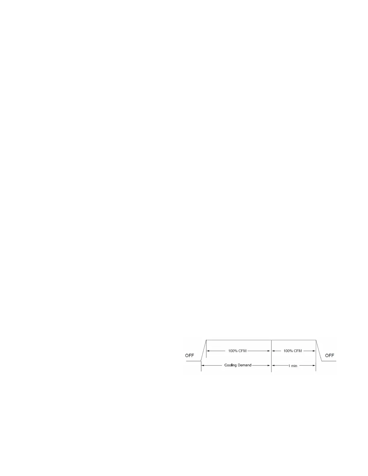
COOL AIRFLOW PROFILE (Cool Profile)
• Profile A provides only an OFF delay of one (1) minute at
100% of the cooling demand airflow.
• Profile B ramps up to full cooling demand airflow by
first stepping up to 50% of the full demand for 30 seconds.
The motor then ramps to 100% of the required airflow. A
one (1) minute OFF delay at 100% of the cooling airflow.