SERVICING
26
communications LED, green receive (Rx) LED, and learn button.
These are described below
a. Red communications LED – Indicates the status of the network.
Refer to the Network Troubleshooting Chart for the LED status
and the corresponding potential problem.
b. Green receive LED – Indicates network traffic. Refer to the
Network Troubleshooting Chart for the LED status and the cor-
responding potential problem.
c. Learn button – Used to reset the network. Depress the button
for approximately 2 seconds to reset the network.
For detail see network troubleshooting section.
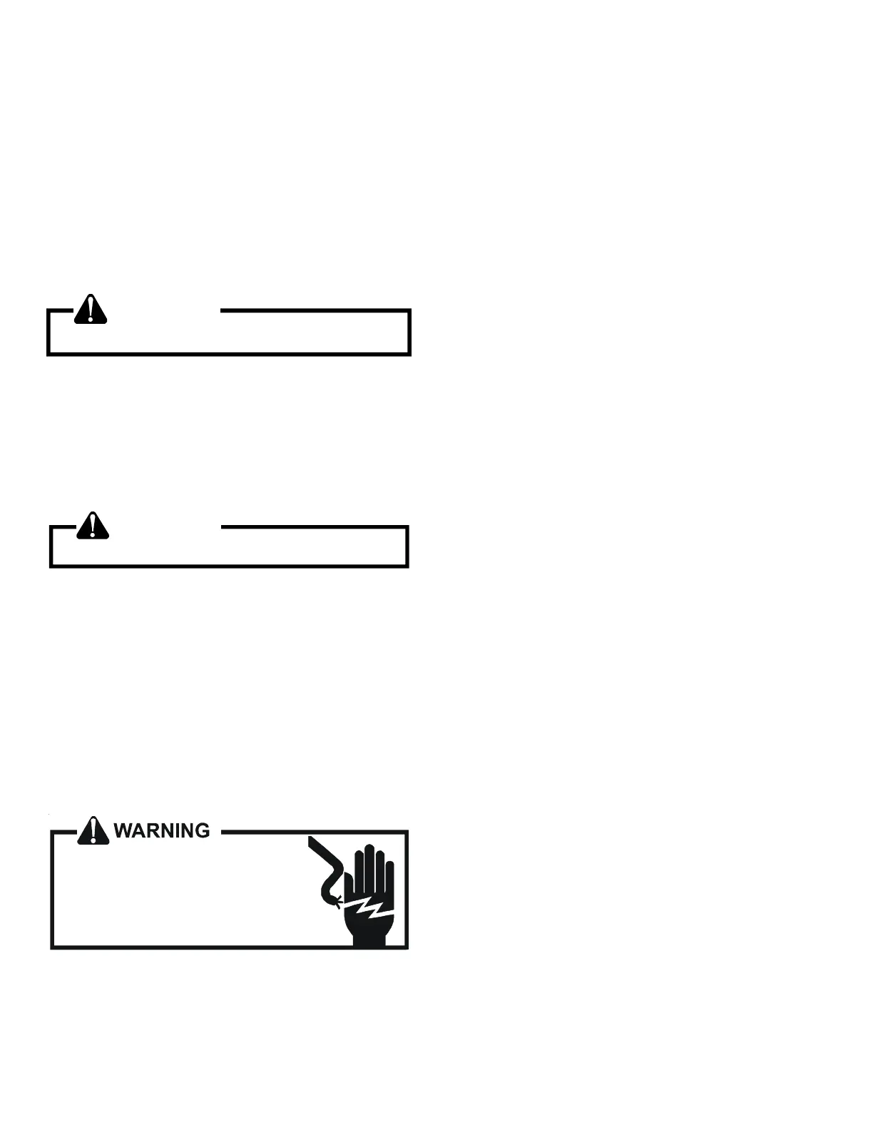
WARNING
Line Voltage now present.
S-50 CHECKING HEATER LIMIT CONTROL(S)
(OPTIONAL ELECTRIC HEATERS)
Each individual heater element is protected with an automatic
rest limit control connected in series with each element to prevent
overheating of components in case of low airflow. This limit con-
trol will open its circuit at approximately 150°F. to 160°F and
close at approximately 110°F.
WARNING
Disconnect ALL power before servicing.
1. Remove the wiring from the control terminals.
2. Using an ohmmeter test for continuity across the normally
closed contacts. No reading indicates the control is open -
replace if necessary. Make sure the limits are cool before
testing.
IF FOUND OPEN - REPLACE - DO NOT WIRE AROUND.
S-52 CHECKING HEATER ELEMENTS
Optional electric heaters may be added, in the quantities shown
in the spec sheet for each model unit, to provide electric resis-
tance heating. Under no condition shall more heaters than the
quantity shown be installed.
HIGH VOLTAGE!
Disconnect ALL power before servicing
or installing. Multiple power sources
may be present. Failure to do so may
cause property damage, personal injury
or death.
1. Disassemble and remove the heating element(s).
2. Visually inspect the heater assembly for any breaks in the
wire or broken insulators.
3. Using an ohmmeter, test the element for continuity - no read-
ing indicates the element is open. Replace as necessary.
S-60 ELECTRIC HEATER (OPTIONAL ITEM)
Optional electric heaters may be added, in the quantities shown
in the specifications section, to provide electric resistance heat-
ing. Under no condition shall more heaters than the quantitity
shown be installed. The low voltage circuit in the air handler is
factory wired and terminates at the location provided for the elec-
tric heater(s). A minimum of field wiring is required to complete
the installation. Other components such as a Heating/Cooling
Thermostat and Outdoor Thermostats are available to complete
the installation.
HEATER KIT CAPACITY SETTING (DV*PEC):
For heater kit installation, it is important to set the capacity of the
electric heater at the communicating thermostat and DIP switch.
SETTING WITH COMMUNICATING THERMOSTAT:
For a detailed procedure of thermostat heater kit capacity selec-
tion process, please visit the DAIKIN ONE+ Smart Thermostat
website at http://www.daikinone.com. (If using a CTK04 thermo-
stat, please see the addendum for further instructions.)
SETTING WITH DIP SWITCH:
In the event of loss of communication, emergency mode can be
activated. In emergency mode operation, heater kit selection will
be driven by the DIP switch (S9, S10, S11, and S12) selection from
the control board on indoor unit. For further detail, read an emer-
gency mode section in this manual.