SERVICING
39
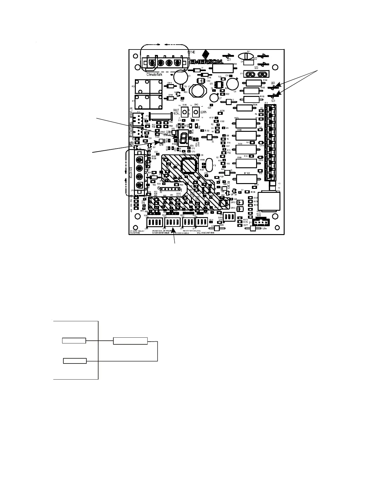
A UXILIARY A LARM S WITCH
The control is equipped with two Auxiliary Alarm terminals,
labeled CAS, which are typically utilized in series with a con-
densate switch but could also be used with compatible CO
2
sensors or fire alarms.
CAS
SWITCH
This feature can be activated or deactivated through the ther-
mostat user menus. The auxiliary alarm switch must be nor-
mally closed and open when the alarm occurs. For example, a
normally closed condensate switch will open when the base
pan’s water level reaches a particular level. The control will
respond by turning off the blower motor and outdoor unit
and displaying the proper fault codes. If the switch is later
detected closed for 30 seconds, normal operation resumes
COM
TH
TR
DE
CAS
HUM
O
R
2
1
C
2
1
ST4
ST3
ST2
ST1
3A
C
Y2
24VAC
FUSE
W1W2
R
C
G
W1
W2
Y1
3
2
Dip Switches
Green CFM LED
Seven Segment
LED
Auxiliary
Alarms
and the error message is removed. The error will be main-
tained in the equipment’s fault history. See FIGURE 15 on the
following page for the connection location.
C IRCULATOR B LOWER
This air handler is equipped with a variable speed circulator
blower. This blower provides several automatically-adjusted
blower speeds. The Specification Sheet applicable to your
model provides an airflow table, showing the relationship
between airflow (CFM) and external static pressure (E.S.P.).
The electric heat dip switch default position is set to the OFF,
OFF, OFF position and should be adjusted by the installer to
match the installation requirements for the correct electric
heating CFM.
Using the Electric Heat Airflow table below, set dip switches 9,
10, and 11 for the installed heater kit. Verify selected CFM by
counting the green CFM LED blinks. The green CFM LED blinks
once for each 100 CFM of airflow.
If an electric heater kit has not been installed, set dip switches
9, 10, and 11 to any appropriate heater kit setting (see next
page table for valid settings).
During the cooling operation, the outdoor unit will determine
the indoor airflow.
Communicating Board
INDOOR UNIT TROUBLESHOOTING FOR TXV APPLICABLE UNIT (MBVC**00AA-1)