SERVICING
24
HIGH VOLTAGE!
Disconnect ALL power before servicing
or installing. Multiple power sources
may be present. Failure to do so may
cause property damage, personal injury
or death.
1. Disconnect power to the heat pump condensor.
2. Disconnect the sensor from the electric board.
3. Connect an ohmmeter across the sensor terminals. The ohm-
meter should read be the resistance shown in the table THER-
MISTOR RESISTANCE AND TEMPERATURE CHARACTERISTICS.
Replace the sensor if the sensor is open, shorted, or outside
the valid resistance range.
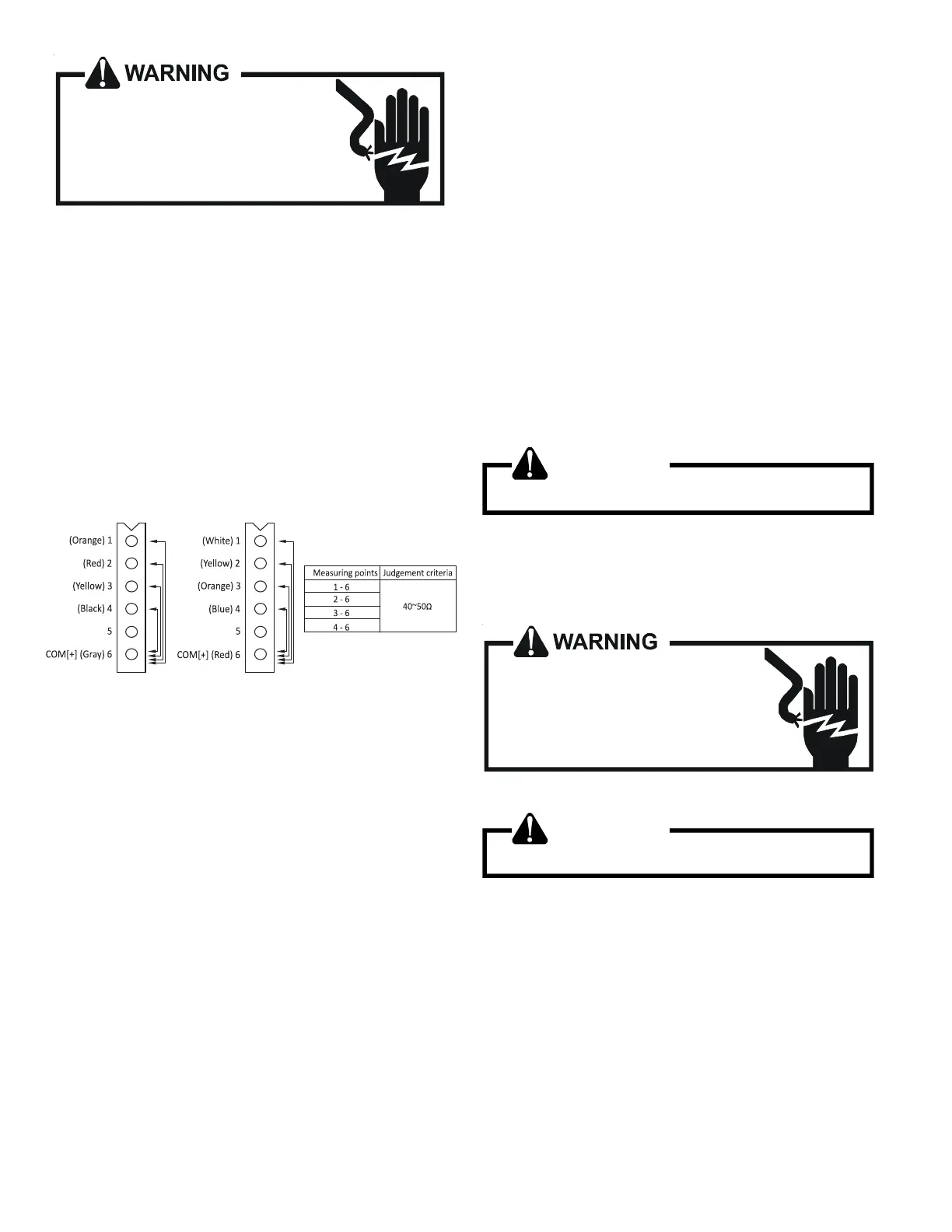
Testing EEV coil resistance
To check the resistance of the EEV coil, first disconnect EEV cable
from the Control board. Make measurements of resistance be-
tween the connector pins, and then make sure the resistance falls
in the range of 40 to 50
Ʊ
.
Outdoor unit: 2 Ton
Outdoor unit: 3. 4. & 5 Ton
Indoor unit: 2, 3, & 5 Ton
S-40A MBVC**00AA-1 Heater Control
Description
The MBVC models utilize an electronic control that provides ECM
blower motor control and control of up to two electric heat se-
quencers. The control has thermostat inputs for up to two stages
of cooling, two stages of electric heat, reversing valve, and dehu-
midification. Control input is 24VAC.
All dipswitches necessary to setup cooling and electric heat air-
flow are fully integrated into the control.
Features
The new air handler control includes advanced diagnostic fea-
tures with fault recall, estimated CFM display via on-board LED,
and thermostat. Diagnostics includes heater kit selection diag-
nostics, open fuse, internal control fault, data errors, and blower
motor faults. Data errors are not included in the fault recall list.
Diagnostic error codes are displayed on a single red LED.
The estimated CFM is displayed on an on-board green LED.
The LED flashes once for each 100 CFM.
The MBVC air handlers may be used in a fully communicating
system when matched with a compatible outdoor unit and the
thermostat. A fully communicating system offers advanced setup
and diagnostic features.
Basic Operation
The air handler control receives thermostat inputs from the
thermostat. The control operates the variable speed blower motor
at the demand as determined from the thermostat input(s). If a
demand for electric heat is received, the control will provide a
24VAC output for up to two electric heat sequencers.
Troubleshooting
Motor Control Circuits
1. Turn on power to air handler or modular.
WARNING
Line Voltage now present.
2. Check voltage between pins 1 and 4 at the 4-wire motor con-
nector on the control board. Voltage should be between 9 and
15 VDC. Replace control if voltage is not as specified.
Electric Heat Sequencer Outputs
HIGH VOLTAGE!
Disconnect ALL power before servicing
or installing. Multiple power sources
may be present. Failure to do so may
cause property damage, personal injury
or death.
1. Turn on power to air handler or modular blower.
WARNING
Line Voltage now present.
2. Disconnect the 4-circuit harness connecting the control to the
electric heater kit.
3. Provide a thermostat demand for low stage auxiliary heat
(W1). Measure the voltage between pins 1 and 3 at the on-
board electric heat connector. Voltage should measure 24VAC.
Replace control if no voltage is present.
NOTE: Allow for any built-in time delays before making voltage
measurements. Any electric heater faults that are present may
prevent the heater output from energizing. Verify that no heater
faults are present before making voltage measurements.