SERVICING
20
S-1 CHECKING VOLTAGE
1. Remove outer case, control panel cover, etc., from unit being
tested.
With power ON:
L
INE
V
OLTAGE
NOW
PRESENT
.
WARNING
2. Using a voltmeter, measure the voltage across terminals L1
and L2 of the contactor for the heat pump condenser unit or
at the field connections for the air handler or heaters.
ComfortNet
TM
Ready Heat Pump Condenser Units: Measure
the voltage across the L1 and L2 lugs on the unitary (UC)
control.
3. No reading - indicates open wiring, open fuse(s) no power or
etc., from unit to fused disconnect service. Repair as needed.
4. With ample voltage at line voltage connectors, energize the
unit.
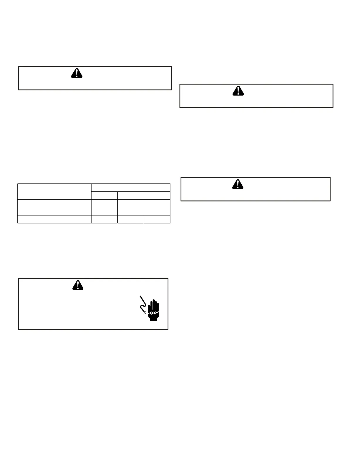
voltage min. max.
Outdoor Unit, Air Handler,
Modular Blower, Heater Kit
208/230 197 253
Gas Furnaces 115 103 126
Unit Suply Voltage (VAC)
Unit Type
NOTE: When operating electric heaters on voltages other than
240 volt, refer to the System Operation section on electric heat-
ers to calculate temperature rise and air flow. Low voltage may
cause insufficient heating.
S-2 CHECKING WIRING
HIGH VOLTAGE !
D
ISCONNECT
ALL
POWER
BEFORE
SERVICING
OR
INSTALLING
. M
ULTIPLE
POWER
SOURCES
MAY
BE
PRESENT
. F
AILURE
TO
DO
SO
MAY
CAUSE
PROPERTY
DAMAGE
,
PERSONAL
INJURY
OR
DEATH
.
WARNING
1. Check wiring visually for signs of overheating, damaged in-
sulation and loose connections.
2. Use an ohmmeter to check continuity of any suspected open
wires.
3. If any wires must be replaced, replace with comparable gauge
and insulation thickness.
S-3 CHECKING THERMOSTAT AND WIRING
Communicating Thermostat Wiring: The maximum wire length
for 18 AWG thermostat wire is 250 feet.
S-3A THERMOSTAT AND WIRING
L
INE
V
OLTAGE
NOW
PRESENT
.
WARNING
With power ON, thermostat calling for cooling/heating.
1. Use a voltmeter to check for 24 volt at thermostat wires C and
R in the indoor unit control panel.
2. No voltage indicates trouble in the thermostat, wiring or trans-
former source.
3. Check the continuity of the thermostat and wiring. Repair or
replace as necessary.
L
INE
V
OLTAGE
NOW
PRESENT
.
WARNING
Resistance Heaters
With power ON:
1. Set room thermostat to a higher setting than room tempera-
ture so both stages call for heat.
2. With voltmeter, check for 24 volt at each heater relay.
3. No voltage indicates the trouble is in the thermostat or wir-
ing.
4. Check the continuity of the thermostat and wiring. Repair or
replace as necessary.
NOTE: Consideration must be given to how the heaters are wired
(O.D.T. and etc.). Also safety devices must be checked for continu-
ity.