SERVICING
40
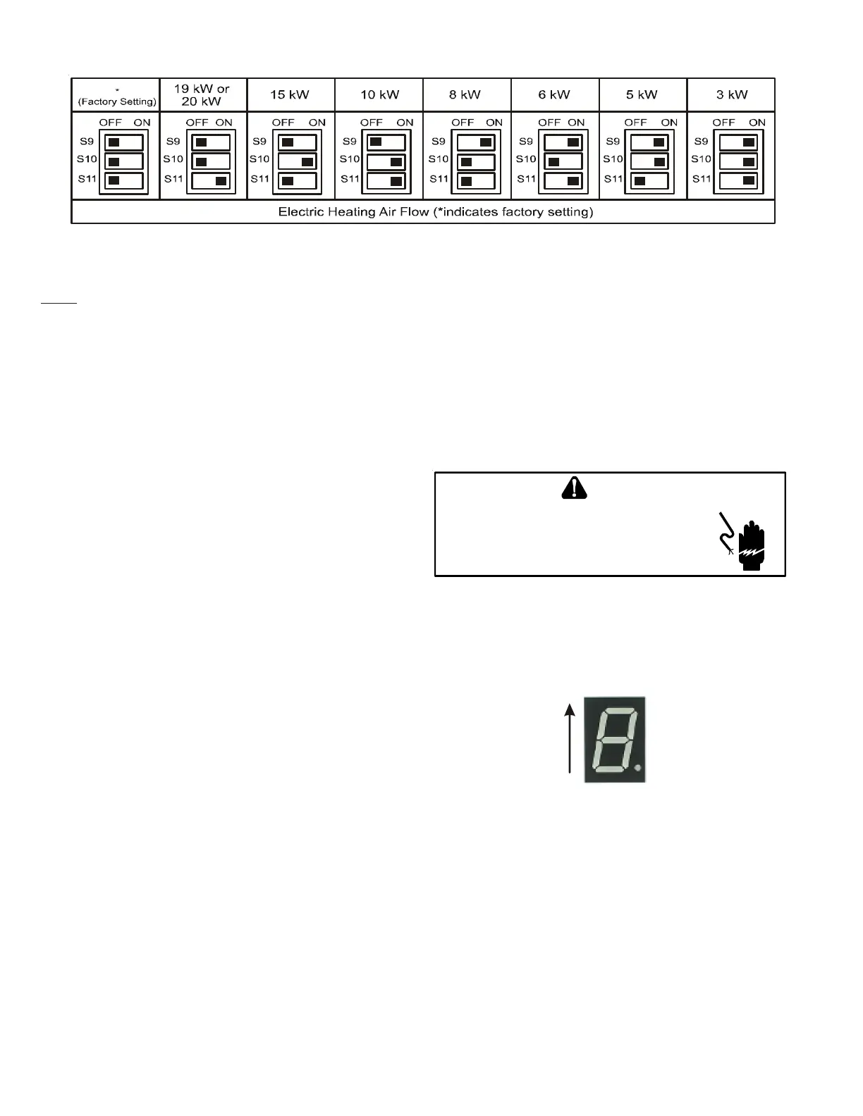
NOTE: Upon start up in communicating mode the circuit board may display an “Ec”
error. This is an indication that the dip switches on the control board need to be
configured in accordance with the Electric Heating Airflow Table. Configuring the
dip switches and resetting power to the unit will clear the error code.
Within the thermostat user menu, CTK04 communicating thermostat will display
20 kW for OFF-OFF-ON dip switch selection.
TROUBLESHOOTING
ELECTROSTATIC D ISCHARGE (ESD) PRECATIONS
NOTE: Discharge body's static electricity before touching unit.
An electrstaic can adversly affect electrical components.
Use the following precautions during air handler installation
and servicing to protect the integrated control module from
damage. By putting the air handler, the control, and ther per-
son at the same electrostatic potentential, these steps will help
avoid exposing the integrated control module to electrostatic
discharge. This procedure is applicable to both installed and
uninstalled (ungrounded) blowers.
1. Disconnect all power to the blower. Do not touch the
integrated control module or any wire connected to the
control prior to discharging your body’s electrostatic
charge to ground.
2. Firmly touch a clean, unpainted, metal surface of the
air handler blower near the control. Any tools held in a
person’s hand during grounding will be discharged.
3. Service integrated control module or connecting wiring
following the discharge process in step 2. Use caution
not to recharge your body with static electricity; (i.e., do
not move or shuffle your feet, do not touch ungrounded
objects, etc.). If you come in contact with an ungrounded
object, repeat step 2 before touching control or wires.
4. Discharge your body to ground before removing a new
control from its container. Follow steps 1 through 3 if
installing the control on a blower. Return any old or
new controls to their containers before touching any
ungrounded object.
DIAGNOSTIC C HART
HIGH VOLTAGE!
T
O
AVOID
PERSONAL
INJURY
OR
DEATH
DUE
TO
ELECTRICAL
SHOCK
,
DISCONNECT
ELECTRICAL
POWER
BEFORE
PERFORMING
ANY
SERVICE
OR
MAINTENANCE
.
WARNING
Refer to the Troubleshooting Chart at the end of this manual for
assistance in determining the source of unit operational prob-
lems. The 7 segment LED display will provide any active fault
codes. An arrow printed next to the display indicates proper
orientation (arrow points to top of display). See following
image.
7 Segment
Diagnostic
Display
FAULT RECALL
The integrated control module is equipped with a momentary
push-button switch that can be used to display the last six
faults on the 7 segment LED display. The control must be in
Standby Mode (no thermostat inputs) to use the feature. De-
press the push-button for approximately two seconds. The LED
display will then display the six most recent faults beginning
with the most recent fault and decrementing to the least recent
fault. The faults may be cleared by depressing the button for
greater than five seconds.
NOTE: Consecutively repeated faults are displayed a maximum
of three times. Example: A clogged return air filter causes the
air handler’s motor to repeatedly enter a limiting condition.
The control will only store this fault the first three consecutive
times the fault occurs.
INDOOR UNIT TROUBLESHOOTING FOR TXV APPLICABLE UNIT (MBVC**00AA-1)