SERVICING
27
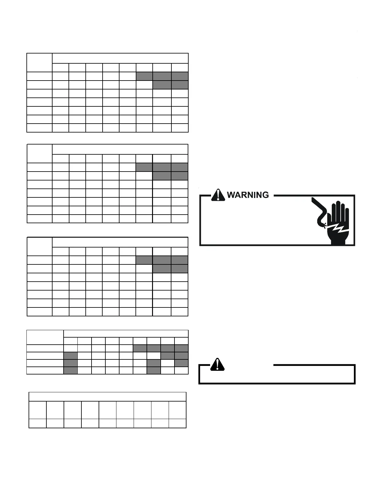
The heating mode temperature rise is dependent upon the system
airflow, the supply voltage, and the heater kit size (kW) selected.
Use data provided in below tables to determine the
temperature rise (°F).
3568101519/2025
800 1219233137
1000 9 15 19 25 30 44
1200 8 12 15 21 25 37 49 62
1400 7 11 13 18 21 32 42 53
1600 6 9 12 15 19 28 37 46
1800 5 8 10 14 16 25 33 41
2000 5 7 9 121522 30 37
CFM
HEAT KIT NOMINAL kW
240/1/60 Supply Voltage - Temp. Rise °F
3 5 6 8 10 15 19/20 25
800 11 18 22 30 35
1000 9 14 18 24 28 42
1200 7 12 15 20 24 35 47 59
1400 6 10 13 17 20 30 40 51
1600 6 9 11 15 18 27 35 44
1800 5 8 10 13 16 24 31 39
2000 4 7 9 12 14 21 28 35
CFM
HEAT KIT NOMINAL kW
230/1/60 SUPPLY VOLTAGE - TEMP. RISE °F
3 5 6 8 10 15 19/20 25
800 10 17 21 28 33
1000 8 13 17 22 27 40
1200 7 11 14 19 22 33 45 56
1400 6 10 12 16 19 29 38 48
1600 5 8 10 14 17 25 33 42
1800 5 7 9 12 15 22 30 37
2000 4 7 8 11 13 20 27 33
CFM
HEAT KIT NOMINAL kW
220/1/60 SUPPLY VOLTAGE - TEMP. RISE °F
35681015192025
DV25PECB14* 550 650 700 715 875
DV37PECC14* 850 900 1000 1120 1220 1250
DV59PECD14* 990 1110 1200 1240 1520 1520
DV61PECD14* 1030 1150 1250 1320 1650 1690 1715
Model
HEATER(kW)
MINIMUM CFM REQUIRED FOR HEATER KITS
HTR
KW
3.0
KW
4.7
KW
6.0
KW
7.0
KW
9.5
KW
14.2
KW
19.5
KW
21.0
KW
BTUH 10200 16200 20400 23800 32400 48600 66500 71600
ELECTRIC HEATER CAPACITY BTUH
For Installations not indicated above the follwing formula is to be
used:
Where: TR = Temperature Rise
kW = Heater Kit Actual kW
3412 = Btu per kW
VC* = 1.0 (240 Supply Volts)
= 0.92 (230 Supply Volts)
= 0.84 (220 Supply Volts)
= 0.77 (210 Supply Volts)
= 0.75 (208 Supply Volts)
1.08 = Constant
CFM = Measured Airflow
TR=(kW x 3412) x (Voltage Correction) / (1.08 x CFM)
*VC(Voltage Correction)
S-61A CHECKING HEATER LIMIT CONTROL(S)
Each individual heater element is protected with a limit control
device connected in series with each element to prevent overheat-
ing of components in case of low airflow. This limit control will
open its circuit at approximately 150°F to 160°F and close at
approximately 110°F.
HIGH VOLTAGE!
Disconnect ALL power before servicing
or installing. Multiple power sources
may be present. Failure to do so may
cause property damage, personal injury
or death.
1. Remove the wiring from the control terminals.
2. Using an ohmmeter, test for continuity across the normally
closed contacts. No reading indicates the control is open -
replace if necessary.
IF FOUND OPEN - REPLACE - DO NOT WIRE AROUND.
S-61B CHECKING HEATER FUSE LINK
(OPTIONAL ELECTRIC HEATERS)
Each individual heater element is protected with a one time fuse
link which is connected in series with the element. The fuse link
will open at approximately 333°F.
WARNING
Disconnect ALL power before servicing.
1. Remove heater element assembly so as to expose fuse link.
2. Using an ohmmeter, test across the fuse link for continuity - no
reading indicates the link is open. Replace as necessary.
NOTE: The link is designed to open at approximately 333°F. DO
NOT WIRE AROUND - determine reason for failure.