75
TROUBLESHOOTING-OUTDOOR UNIT
NETWORK TROUBLESHOOTING
If a network communication error code has occurred, use
the following steps to help troubleshoot the system. (For
network communication error codes, refer to the table below
and the tables of error codes for outdoor unit and indoor
unit.)
After any wiring changes have been made or DS1 dip
switches on the outdoor unit control board have been
changed, apply power to the system and see if the error
codes have cleared.
1. Confirm low voltage wiring is correct per installation
instructions. Check for miswiring. (i.e. Terminal 1 and
2 is reversed.)
NOTE: A removable plug connector is provided with the
control to make thermostat wire connections. This plug
may be removed, wire connections made to the plug, and
replaced. It is
strongly recommended that you do not
connect more than two wires into a single terminal in the
field because there is a risk of the wires becoming loose,
which may result in intermittent operation.
2. Check wires for damage. (i.e. Broken wire at terminal,
broken inside wire nuts or damaged cable between
units.)
3. Perform continuity check on wires to make sure
cable is OK. Replace the cable if necessary.
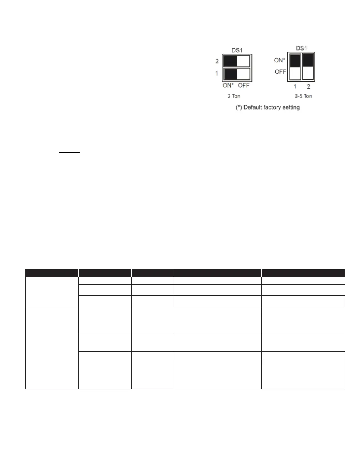
4. Change both dip switches of DS1 on the outdoor unit
control board to the opposite position. See image
above.
The integrated control module has some onboard tools that
can be used to troubleshoot the network. These tools are: red
communications LED, green receive (Rx) LED, and the learn
button.
• Red communications LED – Indicates the status of the
network. The table below indicates the LED status and the
corresponding potential problem.
• Green receive LED – Indicates network traffic. The table
below indicates the LED status and the corresponding
potential problem.
• LEARN button – Used to reset the network. Press the button for
approximately 5 seconds to reset the network.
LED
COLOR LED
Status Indication Probable
Causes Corrective
Actions
Off Normal condition • None • None
1 Flash Communications failure
• Un kn own packet is rec eived
• Communications failure
• Depress learn button
• Verify wiring connection
2 Flash Out-of-box reset
• Co ntrol power up
• Learn button depressed
• None
Off
No power Communications
error
• No power to unit
• Open fuse
• Communication error
• Ch ec k circuit breakers and fuses; Reset/Replace if
needed
• Re set network by depressing learn button
• Ch ec k communication
wires (terminal 1/ t e r m i n a l 2
wires); Replace if needed
• Ch ec k for shorts in low voltage wiring.
1 Steady Flash No network found
• Broken/disconnected communication wire(s)
• Un it is installed as a legacy/traditional system
• Check c ommunic ation wires (terminal 1/terminal 2 wires);
Replac e if needed
• Check installation type (legacy/traditional or
communicating)
Rapid Flashing Normal network traffic • Control is “talking” on network as
expected • None
On Solid
Terminal 1/ T e r m i n a l 2 miss-
wire
• Termin a l 1 and Terminal 2 wires reversed at indoor unit,
thermostat, or outdoor unit
• Sh ort between terminal 1 and terminal 2 wires
• Sh ort between terminal 1 or terminal 2 two wires and
terminal C (24VAC) or terminal R (24VAC, COM)
• Check c ommunic ation wires (terminal 1/terminal 2 wires);
Replac e
if needed
Green Rec eive LED
Outdoor unit control
board:(H2P)
Indoor unit control
board:(H3P)
Red Communications LED
Outdoor unit control
board:(H1P)
Indoor unit control
board:(H2P)