SERVICING
23
Therefore, proper evacuation of a hermetic system is essential at
the time of manufacture and during servicing.
To reduce the possibility of external ignition, all open flame, elec-
trical power, and other heat sources should be extinguished or
turned off prior to servicing a system.
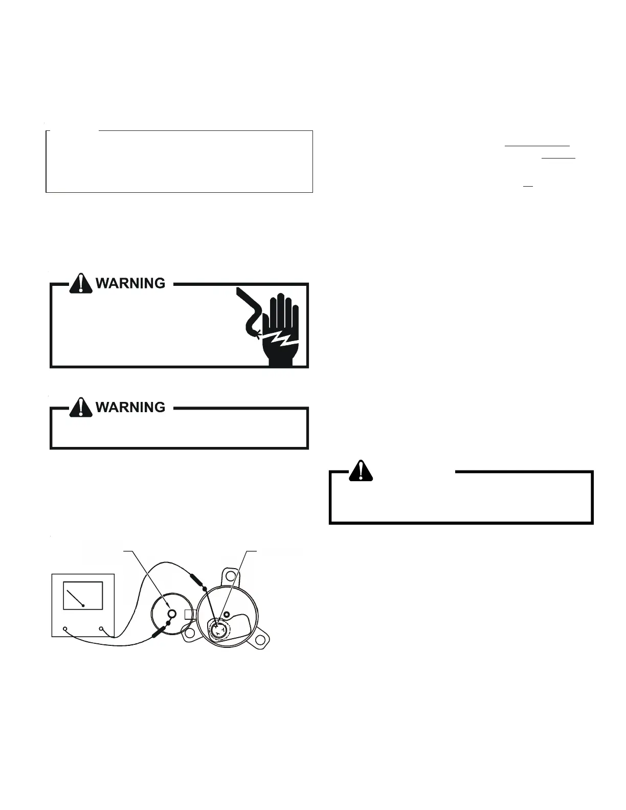
S-17A Resistance Test
HE PECIFICATION OF OR EARLIER MODELS ARE
DIFFERENT FROM THIS SPECIFICATION
OR DETAILS SEE THE SERVICE MANUAL THAT MATCHES THE MAJOR
REVISION OF MODEL NAME
T S DZ20VC0601B*
.
F ,
.
NOTICE
The Inverter on the outdoor control board takes the position sig-
nal from the UVW line, connected with the compressor. If the
system detects a malfunction on the compressor, check the insu-
lation resistance in accordance with the following procedure.
HIGH VOLTAGE!
Disconnect ALL power before servicing
or installing. Multiple power sources
may be present. Failure to do so may
cause property damage, personal injury
or death.
1. Remove the leads from the compressor terminals.
See warnings S-17 before removing compressor
terminal cover.
2. Check the wiring connection of UVW on the compressor termi-
nal.
3. Check the insulation resistance of the compressor between
the compressor terminal and unpainted refrigerant piping.
OHMMETER
Unpainted
Refrigerant
Piping
Compressor
Ter m inal
TESTING COMPRESSOR WINDINGS
If the insulation resistance of the compressor is less than 100 k
Ohms, replace the compressor.
NOTE: If an open compressor is indicated, allow ample time for
the internal overload to reset before replacing compressor.
S-17B GROUND TEST
If fuse, circuit breaker, ground fault protective device, etc., has
tripped, this is a strong indication that an electrical problem
exists and must be found and corrected. The circuit protective
device rating must be checked, and its maximum rating should
coincide with that marked on the equipment nameplate.
With the terminal protective cover in place, it is acceptable to
replace the fuse or reset the circuit breaker ONE TIME ONLY to see
if it was just a nuisance opening. If it opens again, DO NOT con-
tinue to reset.
Disconnect all power to unit, making sure that
all power legs are
open.
1. DO NOT remove protective terminal cover. Disconnect the
three leads going to the compressor terminals at the nearest
point to the compressor.
2. Identify the leads and using an ohmmeter on the R x 10,000
scale or the highest resistance scale on your ohmmeter
check the resistance between each of the three leads
separately to ground (such as an unpainted tube on the
compressor).
3. If a ground is indicated, then carefully remove the compressor
terminal protective cover and inspect for loose leads or
insulation breaks in the lead wires.
4. If no visual problems indicated, carefully remove the leads
at the compressor terminals.
5. Carefully retest for ground, directly between compressor
terminals and ground.
6. If ground is indicated, replace the compressor. The resistance
reading should be infinity. If there is any reading on meter,
there is some continuity to ground and compressor should
be considered defective.
WARNING
Damage can occur to the glass embedded terminals if
the leads are not properly removed. This can result in
terminal and hot oil discharging.
S-26 TESTING TEMPERATURE SENSORS AND EEV COIL
RESISTANCE
The DZ**VC outdoor units and DV**PEC indoor units are factory
equipped with:
• (Ta) an outdoor air temperature sensor
• (Tm) an outdoor coil temperature sensor
• (TI) an outdoor liquid temperature sensor
• (Td) a discharge temperature sensor
• (Tb) a defrost temperature sensor
• (Tgi) an indoor gas temperature sensor
• (Tli) an indoor liquid temperature sensor
To check above sensors: