SERVICING
22
3. No voltage indicates faulty transformer, bad wiring, or bad
splices.
4. Check transformer primary voltage at incoming line voltage
connections and/or splices.
5 If line voltage available at primary voltage side of transformer
and wiring and splices good, transformer is inoperative. Re-
place the transformer.
S-12 CHECKING HIGH PRESSURE SWITCH
HIGH VOLTAGE !
D
ISCONNECT
ALL
POWER
BEFORE
SERVICING
OR
INSTALLING
. M
ULTIPLE
POWER
SOURCES
MAY
BE
PRESENT
. F
AILURE
TO
DO
SO
MAY
CAUSE
PROPERTY
DAMAGE
,
PERSONAL
INJURY
OR
DEATH
.
WARNING
The high pressure switch senses the pressure in the compressor
discharge line. If abnormally high condensing pressures develop,
the contacts of the control open, breaking the control circuit be-
fore the compressor motor overloads. This control is automati-
cally reset.
1. Using an ohmmeter, check across terminals of high pressure
control, with wire removed. If not continuous, the contacts
are open.
2. Attach a gauge to the dill valve port on the base valve.
With power ON:
L
INE
V
OLTAGE
NOW
PRESENT
.
WARNING
3. Start the system in charge mode and place a piece of card-
board in front of the outdoor coil, raising the condensing
pressure.
4. Check pressure at which the high pressure control cuts-out. If
it cuts-out at 605 PSIG to -17 PSIG, it is operating normally
(See causes for high head pressure in Service Problem Analy-
sis Guide). If it cuts out below this pressure range, replace
the control.
S-13 CHECKING INDOOR AND OUTDOOR HI/LOW PRES-
SURE SENSOR
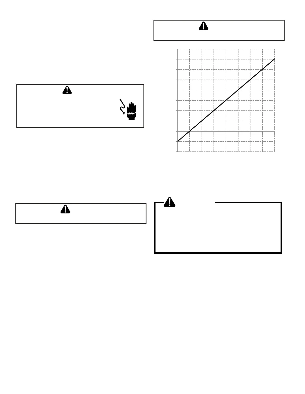
The HI/LOW and indoor pressure sensor senses the suction pres-
sure in cooling mode, and the discharge pressure i heating mode.
Folloe the following sequence to check the pressure sensor. Con-
nect a voltmeter across the sensor terminals between the black
and white wirings. The voltmeter should show the voltage in the
following table. Replace the sensor if the sensor is open, shorted
or outside the valid voltage range.
L
INE
V
OLTAGE
NOW
PRESENT
.
WARNING
-200
-100
0
100
200
300
400
500
600
700
800
0.00.51.01.52.02.53.03.54.0
Detected Pressure (PSIG)
Output Voltage (DCV)
VOLTAGE AND PRESSURE CHARACTERISTICS
S-17 CHECKING COMPRESSOR
WARNING
Hermetic compressor electrical terminal venting can
be dangerous. When insulating material which
supports a hermetic compressor or electrical terminal
suddenly disintegrates due to physical abuse or as a
result of an electrical short between the terminal and
the compressor housing, the terminal may be
expelled, venting the vapor and liquid contents of the
compressor housing and system.
If the compressor terminal PROTECTIVE COVER and gasket (if re-
quired) are not properly in place and secured, there is a remote
possibility if a terminal vents, that the vaporous and liquid dis-
charge can be ignited, spouting flames several feet, causing po-
tentially severe or fatal injury to anyone in its path.
This discharge can be ignited external to the compressor if the
terminal cover is not properly in place and if the discharge im-
pinges on a sufficient heat source.
Ignition of the discharge can also occur at the venting terminal or
inside the compressor, if there is sufficient contaminant air present
in the system and an electrical arc occurs as the terminal vents.
Ignition cannot occur at the venting terminal without the pres-
ence of contaminant air, and cannot occur externally from the
venting terminal without the presence of an external ignition
source.