SiBE041102_A Check
Service Diagnosis 87
5. Check
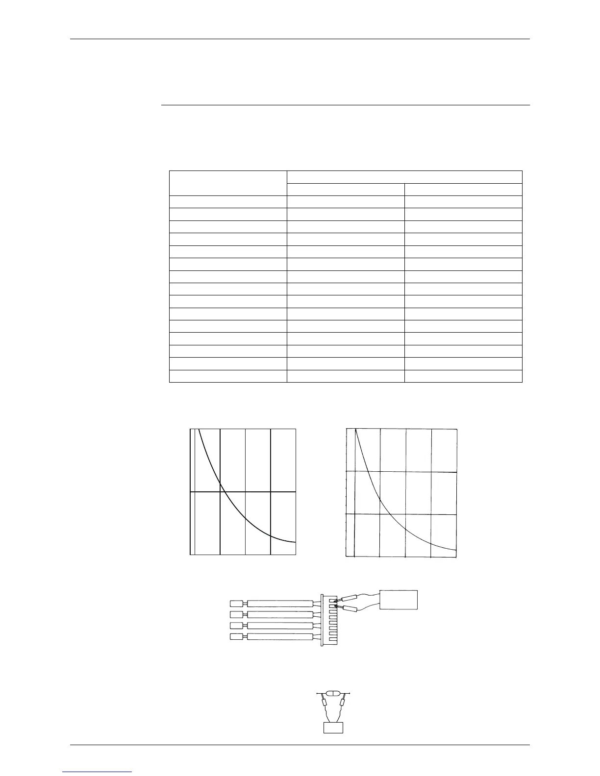
5.1 Thermistor Resistance Check
Check No.01 Disconnect the connectors of the thermistors from the PCB, and measure the resistance of
each thermistor using a tester.
The relationship between normal temperature and resistance is shown in the table and the
graphs below.
For models in which the thermistor is directly mounted on the PCB, disconnect the connector
for the PCB and measure.
Thermistor temperature (°C)
Resistance (k
Ω
)
Room temperature thermistor Other thermistors
–20 73.4 211.0
–15 57.0 150.0
–10 44.7 116.5
–5 35.3 88.0
0 28.2 67.2
5 22.6 51.9
10 18.3 40.0
15 14.8 31.8
20 12.1 25.0
25 10.0 20.0
30 8.2 16.0
35 6.9 13.0
40 5.8 10.6
45 4.9 8.7
50 4.1 7.2
(R25°C = 10 k
Ω
, B = 3435 K) (R25°C = 20 k
Ω
, B = 3950 K)
(11952)
Other thermistorsRoom temperature thermistor
(˚C)(˚C)
50
25
0
–15
0
15 30
45
(kΩ)
(kΩ)
–15
0
15 30
45
150
100
50
Tester
Resistance range
(R11906)
RTH1
Tester
(R3460)
 Loading...