Check SiBE041102_A
88 Service Diagnosis
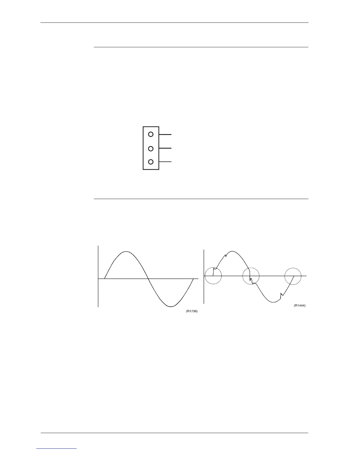
5.2 Hall IC Check
Check No.04 1. Check the connector connection.
2. With the power on, operation off, and the connector connected, check the following.
∗
Output voltage of about 5 V between pins 1 and 3.
∗
Generation of 3 pulses between pins 2 and 3 when the fan motor is operating.
If NG in step 1
Æ
Defective PCB
Æ
Replace the PCB.
If NG in step 2
Æ
Defective Hall IC
Æ
Replace the fan motor.
If OK in both steps 1 and 2
Æ
Replace the PCB.
The connector has 3 pins.
5.3 Power Supply Waveforms Check
Check No.11 Measure the power supply waveform between No. 1 and No. 2 on the terminal board, and check
the waveform disturbance.
Check to see if the power supply waveform is a sine wave. (Fig.1)
Check to see if there is waveform disturbance near the zero cross. (sections circled in Fig.2)
1
Gray (power supply)
Purple (signals)
Blue (grounding)
2
3
(R14211)
S7
Fig.1 Fig.2
 Loading...