12 Installation Manual 3P291714-2B
DCM601A71 intelligent Touch Manager
English
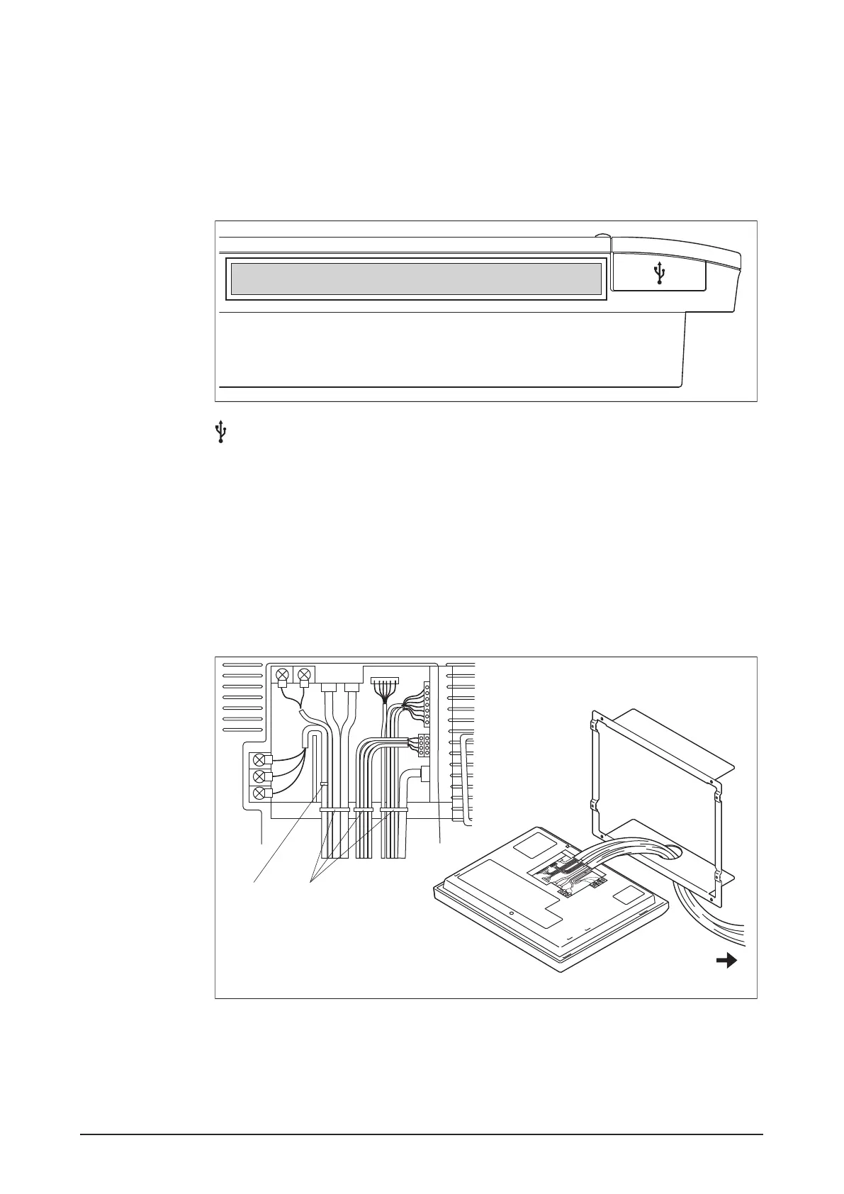
1.3.3 Side face
On the left side of the intelligent Touch Manager, there is a USB port. The USB port is used
for making settings, performing maintenance or other operations after the installation of
the intelligent Touch Manager is completed. Also, on this side a label is attached on which
the information such as product name, weight, power supply and serial number are
printed.
<Side face of intelligent Touch Manager>
[ ] Open this cover to connect the memory to the USB port. This port can be turned 90
degrees to the front direction. You can connect to this port from the front direction if there
is not enough space on the side.
1.3.4 Wiring of cables
To ush-mount the intelligent Touch Manager to the wall, you need to route in advance the
cables through the cable hole of the frame bracket.
The following pictorial wiring diagram (example) shows the state after connections to the
intelligent Touch Manager rear face are completed.
<Pictorial cable wiring diagram (example)>
C
AB
B Clamp
A Push mount tie
C To conduit tube
Be sure to x all cables using the supplied push mount ties.
Fix the power supply cable to the blue resin cable mount using the white clamp, then tie
the cable and other cables with the black push mount tie, as shown in the cable wiring
diagram (example).
When using the black push mount tie, pass its tale through its hole to tie the cables.